Cut-list optimization
Grating Cut Lists: Panel Yield, Offcuts and Bar Direction
Calculate yield from finished pieces and the actual source panel, then keep bearing direction, kerf, edge trim, openings, piece IDs and drawing revision in the same controlled schedule.
Prepared by
Dengtai Industry
Published
·
Reviewed

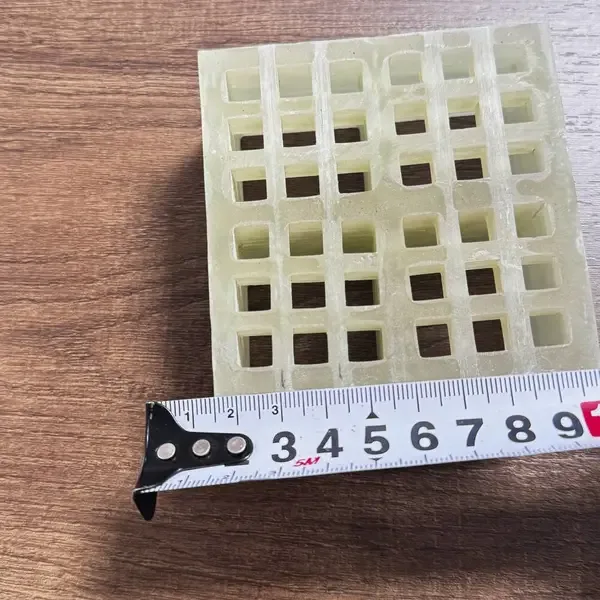
The fabricated pieces and the source panel are two levels of the same order. Photo: Dengtai Industry.
A useful FRP grating cut list identifies both the finished pieces and the source panels they consume. Finished size, quantity, bearing direction, openings, support and edge treatment belong to each piece. Source-panel dimensions, grid or bar direction, kerf and trim belong to the nesting plan. Area yield is calculated only after those fields are connected.
The downloadable CSV on this page is a starting structure, not an approved order. It is prepared and reviewed by Dengtai Industry’s fabrication team so that estimating, factory cutting, inspection and packing can use the same piece IDs.
Download the FRP grating cut-list CSV
The CSV contains clearly marked example rows. Replace them with project piece IDs and keep the drawing revision, support, direction, openings, edge scope and remnant decision visible.

What “Yield” Means in a Grating Cut List
Three different numbers are often called yield:
- Piece-area yield: total area of required finished pieces divided by source-panel area.
- Usable-material yield: required pieces plus approved reusable remnants, divided by source-panel area.
- Commercial yield: the quantity and area basis used in the quotation.
The first is arithmetic. The second requires geometry, direction, quality and a future use for the remnant. The third depends on whether the supplier prices source panels, delivered piece area, cutting, edge sealing and loss separately.
Keep all three visible instead of using one generic yield percentage.
Gross unused area is not automatically an offcut
When one piece is removed from a panel, the remaining material may be:
- a continuous strip that can be identified and stored;
- several small pieces without a future requirement;
- an area containing an opening, defect or damaged edge;
- a directional remnant that cannot be rotated for another piece;
- material consumed by kerf and final edge trim.
Only a controlled remnant list can say whether the unused area is reusable. The cut-to-size piece-list guide handles the finished-part identity; this page adds nesting and yield.
Freeze the Source Panel Before Nesting
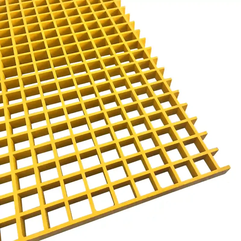
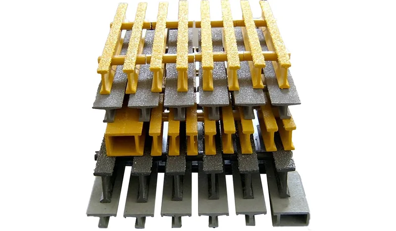
For molded grating, record the actual panel length and width, depth, mesh, resin, surface, color and top face. For pultruded grating, record panel width, bearing-bar length, I/T/WT profile, pitch and cross-rod arrangement.
The source panel should be the product the factory can actually supply. A nominal 4 x 8 ft panel does not necessarily equal 1220 x 2440 mm exactly, and a custom pultruded panel does not share a universal stock-sheet outline. Our fiberglass panel guide explains how the panel row and finished-piece list differ.
Define the nesting coordinate system
Use one drawing datum and one source panel orientation. Mark:
- panel width and length;
- bearing-bar or grid direction;
- top face and any appearance direction;
- trim edge;
- kerf assumption;
- every finished-piece mark;
- rotation;
- openings and support zones;
- remaining strips.
The molded support layout guide and pultruded bearing-bar guide provide the structural drawings the cut list must refer back to.
Worked Example: Four Pieces From One Molded Panel
Assume an illustrative 1220 x 3660 mm molded panel and four finished pieces, each 600 x 1800 mm:
- source area:
1.220 x 3.660 = 4.4652 m²; - piece area:
4 x 0.600 x 1.800 = 4.3200 m²; - gross unused area:
4.4652 - 4.3200 = 0.1452 m²; - area yield:
4.3200 / 4.4652 = about 96.7%.
Two nominal piece columns use 1200 mm of the 1220 mm width. Two 1800 mm rows use 3600 mm of the 3660 mm length. The remaining L-shaped region becomes a 20 mm edge strip and a 60 mm end strip before considering kerf and trim.
Why the percentage is not the release
The 96.7% figure ignores:
- blade kerf;
- exact factory edge trim;
- the finished-size tolerance;
- top-face restrictions;
- grid or bearing direction;
- any opening in a finished piece;
- whether a 20 mm strip has a future use;
- whether each finished piece has effective support.
The area calculation is still useful. It makes the relationship between pieces and source panel visible. It simply cannot substitute for the drawing and support review.
Estimate mass from a confirmed product basis
The downloadable CSV includes estimated_piece_mass_kg and mass_basis. These fields keep a weight estimate usable without turning it into an unsupported approval.
Mass is a separate calculation from area yield. A 96.7% layout shows how much of the source panel becomes named finished pieces. It does not show how much those pieces weigh, and it does not turn unused area into delivered material. Start with the exact molded, mini-mesh or pultruded row the factory can supply. Use its confirmed mass per unit area or unit length, apply the finished-piece geometry, and record that source in mass_basis.
If the current row or mass basis is not confirmed, leave the estimate marked TBC. Do not calculate a number from a generic material density or copy another product family’s weight. The FRP grating weight guide and molded panel weight method explain how product row, thickness, mesh and finished size affect the result.
Piece mass is also not package gross mass. Clips, edge treatment, separators, labels, pallets, crates and any delivered remnants can change the shipping calculation. Keep the piece estimate in the cut-list schedule and calculate the package gross mass in the packing record.
Direction Changes What “Fits” Means
Pultruded grating
The principal load path follows the bearing bars. Each load-bearing bar must run between effective supports, and the bar ends must bear. A piece can fit the rectangle after a 90-degree rotation while no longer spanning as intended.
Mark bearing direction on the cut piece itself and in the packing identity. The pultruded cut-end guide explains the end condition, while the span and deflection guide shows why rotation can invalidate the supporting data.
Molded and mini mesh grating
Square molded mesh can look symmetric, but the selected row, rectangular long-way-of-opening, surface pattern, top face and piece orientation may still matter. A double-layer mini mesh also has an upper and lower grid. Record the approved face and any restriction instead of assuming rotation is harmless.
Cutouts interrupt the layout
An opening can remove several bars or part of the top grid. It can also change the required support around the cut and the usable remnant. Mark removed bars and opening support on the same layout; sealing is not a structural reinstatement.
Classify Every Offcut Before Calling It Reusable
Use three statuses:
| Status | What it means | Record required |
|---|---|---|
| Approved reusable candidate | The remnant has a defined future piece, size, direction and condition | Remnant ID, product row, dimensions, condition and owner |
| Project remnant | Material is retained for a possible change, but no final piece is approved | Storage location and review date |
| Scrap | Direction, size, damage, contamination or lack of use makes it non-reusable | Reason and disposal/recycling route |
An unlabeled strip is not a reusable remnant because no one can prove its row, orientation or history. The repeat-order traceability guide shows a similar principle for appearance samples: future use depends on a retained identity.

Release the Cut List With the Drawing, Quote and Packing List
The same piece IDs should appear in:
- the installation layout;
- the cut-list schedule;
- the quotation or priced item schedule;
- the factory drawing and nesting plan;
- the first-piece or inspection record;
- labels and the packing list.
If the drawing has revision B, the cut list should not still be based on revision A. If a piece changes direction or top face, it needs a visible revision even if its length and width remain unchanged.
The quotation comparison guide explains how to compare sheet consumption, delivered area, cutting, edge treatment and packing between suppliers. The export unit guide carries the piece count into package records.

Our Factory View: Optimize the Real Product, Not Only the Rectangle
Our cutting review starts with the source row and the approved layout. We need to know whether rotation is permitted, how the piece is supported, where bars are interrupted and which edges require sealing.
We then compare nesting options while keeping the finished-piece IDs visible. A layout that increases area yield but creates a narrow unsupported strip, an unapproved rotation or a difficult lift is not automatically the better fabrication plan.
For the quotation, show how the supplier handles:
- source-panel quantity and actual dimensions;
- delivered piece area;
- kerf and trim;
- cutting and edge treatment;
- piece marking or labels;
- approved remnants;
- packing and freight.
That creates a cut list that can be optimized, quoted, produced and checked against the same geometry.
Get a Quote
Get a Grating Cut Lists: Panel Yield, Offcuts and Bar Direction Quote
- Attach the drawing revision
- Keep source panels separate from pieces
- Mark direction on every affected piece
Worked example
Calculate Area Yield Before Calling an Offcut Reusable
The arithmetic is simple; the release decision is not.
| Worked-example value | Calculation | Result |
|---|---|---|
| Source panel | 1.220 m x 3.660 m | 4.4652 m² |
| Finished pieces | 4 x (0.600 m x 1.800 m) | 4.3200 m² |
| Unused area | 4.4652 - 4.3200 | 0.1452 m² |
| Area yield | 4.3200 / 4.4652 | About 96.7% |
| Kerf and trim | Not included in the area subtraction | Deduct from usable pieces and remnants |
| Final usable yield | Requires the approved nesting and remnant list | Not established by area alone |
Construction
How Cutting and Yield Change With Molded or Pultruded Grating
Direction and source-panel format change what rotation and nesting mean.
| Cut-list issue | Molded grating | Pultruded grating | Release question |
|---|---|---|---|
| Main direction | Grid pattern, rectangular long-way-of-opening and top face | Parallel bearing bars must run between effective supports | Is direction marked against one project datum? |
| Source panel | Standard sheet sizes and molded row | Custom panel width and bearing-bar length | Does the nesting use the actual supplied panel? |
| Rotation | May change grid orientation, appearance and support direction | Can change the span path and end bearing | Is rotation permitted per piece? |
| Openings | Cut grid bars and top surface | Interrupt bearing bars and cross rods | Which bars are removed and what supports remain? |
| Edge | Molded cut face and surface edge | Bearing-bar end, cross-rod end and cut edge | Which faces are sealed or finished? |
| Offcut | May be reusable only with the same row and direction | May retain directional bars but not necessarily the required span | Is the remnant approved, traceable or scrap? |
Schedule
Fields That Turn a Cut List Into a Production Record
Twelve fields keep the finished part connected to its drawing, support and package.
| Cut-list field | Required record | Why it matters |
|---|---|---|
| Piece ID | Unique mark tied to the layout and drawing | Prevents equal outlines from being treated as interchangeable |
| Finished size | Length, width, unit and tolerance | Defines what the factory is required to deliver |
| Quantity | Finished-piece count, not source-panel count | Prevents quote quantity ambiguity |
| Product row | Construction, depth or bar profile, mesh or pitch, resin and surface | A size alone cannot identify the product |
| Direction | Bearing bars or grid orientation marked from one datum | A rotated piece may no longer match the support design |
| Support and span | Supported edges, clear span and bearing | Nesting cannot approve the structure |
| Openings and holes | Size, position from datum and support around the cut | Removed bars change the local load path |
| Edge treatment | Faces to seal, finish or leave cut | “Edge sealed” is not a complete scope |
| Top face | Surface direction or appearance side if applicable | Prevents handed pieces from being flipped |
| Drawing revision | Current controlled reference | Prevents mixed revisions from entering one nesting plan |
| Offcut disposition | Reusable candidate, project remnant or scrap | Prevents an unverified remainder from being promised again |
| Mark and pack | Label, bundle and packing requirement | Connects the cut list to receiving and installation |
Planning sequence
From Drawing Revision to Released Cut List
Nest the actual product, then classify the geometry that remains.
Confirm construction, source-panel dimensions, mesh or bearing-bar direction, top face and drawing revision.
Assign IDs and record finished size, quantity, direction, support, openings and edge scope.
Place every piece with its rotation and trim allowance; show kerf and expected edge trim.
Calculate piece area, gross offcut area and area yield, then list the actual offcut shapes.
Decide whether each remainder is an approved reusable candidate, a project remnant or scrap.
Identify removed bars, unsupported edges, narrow strips and openings that require engineering review.
Match the cut list, drawing, quotation, inspection sheet and packing list to the same piece IDs and revision.
- Controlled drawing — One current layout and support drawing with revision and dimensions measured from a stated datum.
- Source panel — Product row, actual source dimensions, mesh or bearing-bar direction and required top face.
- Finished-piece IDs — Unique IDs for every handed, rotated, notched or different piece.
- Finished dimensions — Length, width, quantity, unit and tolerance for each piece.
- Direction and support — Bearing bars or grid orientation, supported edges, clear span and bearing width.
- Openings and holes — Location, size, object clearance, removed bars and support around every opening.
- Edge scope — Faces to seal or finish and required inspection evidence.
- Kerf and trim — Factory cutting allowance, edge trim and any project-specified dimensional tolerance.
- Remnant rule — What may be reused and what remains part of the same project.
- Piece marking — Marking method, orientation mark and label attached to the packing list.
FRP Grating Cut List and Yield Questions
What is panel yield for FRP grating?
Is a high area yield always a good layout?
Can I rotate a molded grating piece?
Can I rotate a pultruded grating piece?
Is the 96.7% example a quotation or production result?
Does the cut-list CSV calculate weight from area yield?
Can an offcut be reused later?
What does a cutting list need besides sizes?
Does cutting or sealing restore interrupted bars?
Why does source-panel size matter if the factory cuts to the piece list?
What is the best first file to send?
Boundary
What Area Yield Does Not Approve
High yield cannot replace direction, support, load or remnant review.
- Yield boundary — Area yield is a planning metric. It does not approve support, load, deflection, minimum piece size, rotation or remnant use.
- Piece identity — Every unique finished part needs its own ID and direction mark, even when its length and width match another piece.
- Fabrication source — Grating Pacific's fabrication and layout guidance highlights stock panel widths and bearing-bar direction as inputs to efficient layout and support planning. Review Grating Pacific layout and manufacturing guidance
- Ordering-field source — McNICHOLS separates product construction, grid or bar direction, panel or cut pieces, fabrication, accessories and tolerances in its ordering method. Review McNICHOLS fiberglass grating ordering fields
This content was prepared and reviewed by Dengtai Industry’s technical and production team using the project conditions, available product data and applicable documents. Limits that require design, testing or approval are identified in the content. Content last checked: