Pultruded grating fabrication guide
Cut Ends and Cross-Rods in Pultruded Grating Fabrication
A finished end is not only a trimmed outline. Check the bearing-bar length, cross rods, intended support, cut quality, edge treatment and piece identity as one fabrication record.
Prepared by
Dengtai Industry
Published
·
Reviewed

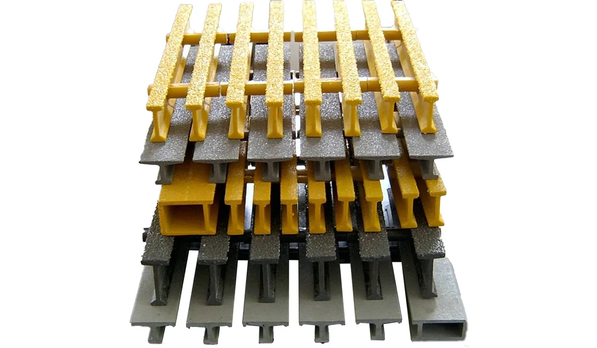
The cut ends reveal the section and assembly geometry that the finished piece must retain. Photo: Dengtai Industry.
Cut-end terms
Bearing Bars, Cross Rods and the Finished Cut Face
Separate the load path from the connecting assembly and the surface protection step.
- Bearing bar
- The continuous pultruded member that carries the principal load along its length. Its end must reach the effective support shown by the structural arrangement.
- Cross rod
- A transverse member that connects and stabilizes the bearing bars. Contact with a cross rod is not normally an equivalent bearing support.
- Cut end
- The finished edge created by trimming the panel or cutting a bearing bar. It includes the geometric edge, the exposed laminate and the related support condition.
- Cross-rod datum
- A stated position from an end or feature from which cross-rod spacing, joint alignment or fixing positions are measured.
- Edge sealing
- A compatible resin treatment applied to a cut or drilled face to protect the exposed laminate. It does not restore a severed bearing bar or create support.
- Structural splice or repair
- Work intended to re-form or reconnect a structural member. It is separate from edge sealing and requires its own geometry, resin, load-path, processing, cure and inspection review before it can be included in an order.
- Finished-piece release
- The record confirming that the correct drawing revision, dimensions, bars, rods, cut face and treatment have been inspected before the piece is packed.
Feature comparison
What Changes When a Pultruded Panel Is Cut
A new edge can affect geometry, load path, treatment and identity at the same time.
Swipe horizontally to view all columns.
| Feature or condition | Function | What a cut can change |
|---|---|---|
| Bearing bar | Carries the principal span load. | Length, squareness, continuity and support at both ends must match the approved piece. |
| Cross rod | Connects and stabilizes parallel bearing bars. | Its spacing, connection and distance from the cut need review, but it does not become a bearing end. |
| Source-panel end | Original outside boundary of the assembled panel. | Cutting may create a new edge with a different relationship to bars, rods and supports. |
| Opening edge | Boundary around a pipe, duct or access opening. | Interrupted bearing bars may need a new perimeter support shown by the drawing. |
| Cut face | Exposed laminate at the finished edge. | Cutting can create chips, exposed fiber or loose material that require inspection and treatment. |
| Cutting process | Physical separation of bars, rods and surrounding material to the finished line. | Poor support, feed or blade condition can bow the assembly, burn resin or tear the edge. |
| Edge sealer | Helps protect the exposed cut face when specified. | It can make the edge more durable, but cannot restore bar continuity or bearing. |
| Structural repair | Re-forms or reconnects material intended to carry structural load. | A repair method and its evidence must be approved separately; an edge-seal coat is not structural work. |
Inspection matrix
Eight Fields for a Finished Pultruded Cut End
Record what the piece is, where the load bars end and how the cut face is released.
Swipe horizontally to view all columns.
| Inspection field | What to inspect | Evidence to keep |
|---|---|---|
| Drawing identity | Current revision, piece mark, top face and bearing direction. | Drawing issue used for fabrication and a matching piece schedule. |
| Finished geometry | Width, bearing-bar length, square or angled end and required datum. | Measured result against the agreed dimension and tolerance. |
| Bar continuity | Which bearing bars remain continuous and which were interrupted by openings. | Marked opening ID and the support or frame required by the drawing. |
| Cross rods | Spacing, end offsets, connection condition and required alignment. | Record of the approved assembly datum rather than a photograph alone. |
| Cut face | Chips, cracks, delamination, exposed fiber and loose material. | Inspection note for the specific piece or agreed sample. |
| Edge treatment | Which faces are sealed and whether the coating is continuous and cured. | Sealer type or batch reference and the applied-face scope. |
| Piece marking | The physical item can be matched to the drawing and packing list. | Legible mark retained through inspection and packing. |
| Final disposition | Pass, hold, rework or another controlled result. | Inspector, date and acceptance note. |
A pultruded grating cut end should be checked as part of the complete finished piece. Confirm the piece mark and drawing revision, the bearing-bar length and direction, the cross-rod condition, the required support, the cut-face quality and the agreed edge treatment.
The inspection is not complete when the edge looks clean. A sealed edge can still belong to a piece with an interrupted bar, missing support or the wrong cross-rod datum.

Identify What Is Being Cut
There are several different “ends” on a fabricated pultruded order:
- the outside end of the complete panel;
- a new end created by trimming the panel width or bearing-bar length;
- an interrupted bar end beside an opening;
- a cross rod cut near an opening or edge;
- an angled or notched edge;
- a loose piece intended for a removable panel.
Record which condition applies before inspection. A generic note to “trim to size” does not say how the bearing bars and cross rods relate to the support.
Use the bearing-direction guide to tie the lead bar length and arrow to a fixed project datum. Use the bar-spacing guide when cross-rod spacing or clear opening is also being checked.
Cut the Pultruded Assembly With Support and Control
Factory cutting is our preferred route when the finished dimensions are known. The cut list can be checked against the profile, bearing direction, cross-rod datum and opening support before the work starts. It also keeps edge treatment and piece identification under the same fabrication record. Use the cut-to-size piece-list guide to add marks, quantities and opening coordinates, and the factory-cut versus site-cut review when the fabrication location is still open.
Where a pultruded piece does need to be cut on site, the method still has to respect the assembled structure:
- mark from the approved datum and allow for the actual blade kerf;
- support both the piece being kept and the waste piece close to the cut line;
- clamp the work and use a guide for a long straight trim;
- use a blade and tool intended for composite material, following the manufacturer’s instructions;
- keep a controlled feed and stop if the panel bows, the blade grabs, the edge tears or the resin starts to burn;
- keep the tool square to the panel so the finished end does not become an unintended bevel;
- use extraction or ventilation and the eye, respiratory, skin and clothing protection required by the site assessment.
The general FRP cutting guide shows the usual tool families: a guided circular or track saw for a long straight trim, a jigsaw or reciprocating saw for curves and notches, and a hole saw for round openings. These are starting points; the blade, speed and feed still have to suit the actual section and surface.
For repeated pieces, measure the first cut before running the set. A trial cut on an offcut is especially useful when a special surface, coating or unfamiliar blade is involved. Do not use a flame or uncontrolled heat source to cut or soften the grating.
The cut is complete only when the geometry, bar condition, cross rods and support have been checked. A neat-looking line does not replace that inspection.
Keep Cross Rods in the Assembly Scope
Cross rods connect and stabilize the parallel bearing bars. They are not normally an alternative load-bearing span direction.
At a finished end, check:
- the specified cross-rod spacing;
- the distance from the end to the nearest rod;
- whether adjacent pieces need their rods aligned;
- whether a fixing or opening dimension is measured from a rod;
- that the connection remains sound near trimming or drilling;
- whether the cutting method may disturb the cross-rod assembly.
The cross-rod spacing belongs on the custom assembly drawing. It should not be inferred from bearing-bar pitch or copied from another supplier’s panel.
A Cross Rod Is Not Bearing
A bearing bar supports load through the end that rests on a structural member. A cross rod may touch a frame or be clamped to it, but that contact does not automatically make the rod an effective bearing line.
If the panel design calls for support from a cross-rod side, that condition must be stated and supported by the project design. It cannot be created by how the panel happens to sit after cutting.
Check the Bearing-Bar End Against the Support
Trace the bearing bars to both intended support faces. The finished bar length is only correct if:
- the piece is oriented correctly;
- the span dimension matches the support drawing;
- the bearing-bar ends reach the available bearing seats;
- distortion or an edge trim does not hold the bars away from the support;
- no opening has left a bar with an unsupported remaining end.
The same-duty span guide explains why panel length and clear span are not interchangeable. A cut piece can fit the outline yet miss the designed bearing.
Separate Cut-Face Quality From Structural Condition
The cut face can show:
- chips along the edge;
- cracks or delamination;
- exposed reinforcement;
- loose material;
- surface damage or roughness.
Recording the edge condition is necessary, but it does not replace checking the bar continuity and support. A visually neat edge can still be structurally wrong; a rough edge may also hide damage that needs rework.
Agreement should cover the acceptable appearance and the local condition at the end, not only a photograph of the finished face.
Specify Edge Sealing by Face
If edge treatment is required, state whether it applies to:
- full perimeter;
- trimmed bearing-bar ends;
- opening edges only;
- drilled hole walls;
- several of these.
The sealer should be compatible with the ordered resin and function. The factory can provide resin sealing when requested; the exact scope and cost are part of the fabrication offer.
Sealing should follow a cleaned and inspected face. It should not cover a crack, wick into delamination or become the visual substitute for an unreviewed structural cut.
Resin sealing, glass-fibre work, filling and structural splicing are not interchangeable labels. An edge coat protects the exposed laminate. If the proposal is to re-form or reconnect a structural member, the joint geometry, load path, resin compatibility, laminate build, cure and inspection must be approved as a separate manufacturing scope before the work is quoted or performed.
For the complete record behind a protective edge treatment, use the face-by-face FRP grating edge-sealing guide. It separates coverage, cure and inspection from structural repair.
Inspect Cross Rods Near Openings and Edges
An opening may also alter the local cross-rod layout. Check:
- whether a rod remains in the component;
- whether the cut end of a rod is exposed;
- whether the end-to-rod offset matches the assembly drawing;
- whether the connection to adjacent bearing bars is intact;
- whether the rod has been disturbed by drilling or cutting;
- whether edge treatment is required over the local cut faces.
Do not assume a cut near a rod has the same condition as an interrupted bearing bar. Record each feature separately.
Use the Sample or First Piece as a Control
When the order includes repeated pieces, a controlled first-piece check can confirm:
- the revision and piece mark;
- the finished dimensions;
- bearing-bar continuity;
- cross-rod datum;
- cut-face appearance;
- sealing scope;
- marking and packing method.
An approved sample should be tied to the same product row and drawing revision. It is not automatically representative after the profile, resin, assembly or cut geometry changes.

Record Pass, Hold or Rework
A useful inspection record does not need a “pass” tick for appearance only. It should show:
- the item inspected;
- the drawing revision;
- the measured or checked fields;
- any nonconformance;
- the disposition;
- who released it and when.
If a critical dimension, interrupted bar or support condition is unresolved, the correct disposition is hold or rework, not “seal and proceed.”
The Cut-End Rule
Start with the correct piece and bearing direction. Confirm the finished bar length, cross-rod condition and support. Inspect the cut face. Apply the agreed edge treatment. Keep the piece mark through packing.
That is the minimum scope for a pultruded cut end to be treated as a released fabricated component instead of a trimmed panel.
Inspection sequence
From Released Drawing to Packed Piece
Verify identity and support before accepting the appearance of the cut edge.
Confirm revision, piece mark, direction, finished dimensions and opening list.
Trace both ends of each load-bearing bar to the intended support lines.
Mark where an opening or trim breaks the bar and confirm the required support.
Verify spacing, offsets, alignment and connection condition against the assembly drawing.
Hold the drawing, bar direction, tool, guide and both sides of the cut stable; stop if the edge tears or resin burns.
Look for chips, cracks, exposed fiber and loose material before sealing.
Confirm the edge treatment, mark the piece and record pass, hold or rework.
Release boundary
What Must Be True Before a Cut Piece Ships
The piece, support condition, cross-rod assembly and treatment scope must remain connected.

Correct piece
The piece mark, drawing revision, top face and bearing direction match the release package.
Correct end support
The finished bearing-bar ends reach the support assumed by the design.
Correct opening condition
Interrupted bars and any added perimeter support are identified on the drawing.
Correct cross-rod assembly
Spacing, offsets, alignment and connection conditions are checked against the assembly information.
Correct cut-face treatment
The inspected face is protected to the agreed scope without claiming structural restoration.
Correct dispatch identity
The physical piece remains identified through packing and site receiving.
RFQ checklist
What to Send With a Pultruded Cut List
Show the geometry, direction, support, cross rods and edge-treatment requirement.
- Finished-piece drawing — Every outline, opening, bearing direction, top face and revision shown from a stated datum.
- Cut list — Piece mark, width, bearing-bar length, quantity, edge condition and required mark.
- Support layout — Effective supports, bearing faces, joints and opening frames.
- Cross-rod requirement — Spacing, end offsets, required joint alignment and any fixing position tied to a rod.
- Edge-treatment scope — Faces to seal, required appearance, compatibility requirement and inspection method.
- Cutting method and controls — Factory or site route, proposed tool and blade, support, dust control and the first-piece check.
- Structural-repair scope — Any proposed splice, hand-lamination or load-path repair, stated separately from ordinary edge sealing.
- Tolerance and acceptance — Dimensions and cut quality the project will accept, without assuming a universal tolerance.
- Packing requirement — Piece grouping, edge protection, marking and package identification.
- Required record — Whether the project needs a first-piece record, measured result, photo or inspection report.
Request fabrication
Send Your Pultruded Cut Drawing
Upload the piece list and identify which dimensions, bars and edges control acceptance.
- Bearing-bar and cross-rod conditions separated
- Cut faces and sealing scope identified
- Piece marks carried into packing
Pultruded Grating Cut-End Questions
What should I inspect on a cut pultruded grating end?
Is a cross rod the same as a bearing-bar end?
Does sealing a cut end restore a cut bearing bar?
Should every pultruded cut edge be sealed?
Where should cross-rod spacing be measured from?
Can I cut a pultruded panel on site?
How should a pultruded grating piece be supported during cutting?
Does resin sealing repair a structural joint?
What happens if an opening cuts a bearing bar?
Can two cut pieces with the same outline be interchangeable?
Which dimensions should be marked as critical?
Can you inspect and record a cut pultruded piece?
This content was prepared and reviewed by Dengtai Industry’s technical and production team using the project conditions, available product data and applicable documents. Limits that require design, testing or approval are identified in the content. Content last checked: