Pultruded grating engineering guide
Pultruded Grating Span and Deflection: Comparing the Same Duty
A deflection value cannot be carried from one product, span or support condition to another. Fix the project duty first, then compare the exact pultruded section and finished panel against matching evidence.
Prepared by
Dengtai Industry
Published
·
Reviewed

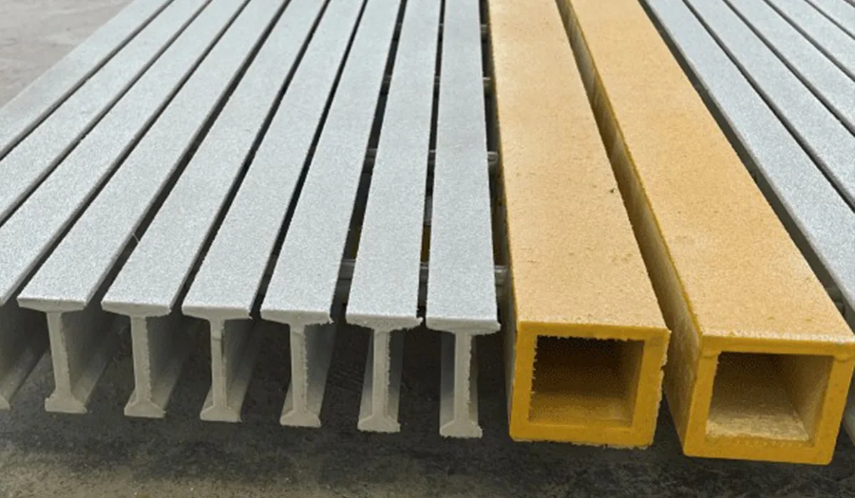
The bearing direction, section and assembly are part of the span check. Photo: Dengtai Industry.
Span vocabulary
Clear Span, Bearing, Load and Deflection
These fields describe different physical conditions and cannot be replaced by a single nominal panel size.
- Clear span
- The unsupported distance between the effective bearing faces. It is not automatically the panel length, the outside frame size or the distance between fastener centers.
- End bearing
- The length of each bearing-bar end that rests on an effective support. Contact with a loose trim, a clip or a cross rod does not automatically provide bearing under the load bars.
- Load pattern
- How the load reaches the panel: uniform area load, concentrated line load, point load, wheel load or another stated arrangement, including location and duration.
- Deflection
- Movement of the grating under a defined load and support condition. It must be read with the load at which it occurs and the project’s acceptance limit.
- Recommended, design and ultimate values
- Three different bases for a published number. An ultimate result is not automatically an allowable working load, and a recommended value still depends on its stated support, load and service assumptions.
- Same-duty comparison
- A comparison that keeps the project span, bearing, loading, deflection limit, exposure and finished-panel geometry fixed while changing only the product variable being evaluated.
Value audit
What a Pultruded Grating Span Comparison Must Match
A copied value becomes unsafe to interpret when even one structural input changes.
Swipe horizontally to view all columns.
| Field | What to compare | Why copying a nearby value fails |
|---|---|---|
| Span definition | Use the same measured clear span or the table’s stated span basis on every candidate. | A panel that fits a 1200 mm frame opening may bear over a different clear distance. |
| Section and pitch | Identify the exact I, T or WT profile, depth, top width and bearing-bar pitch. | Two 38 mm profiles can have different flange geometry, pitch, mass and section behavior. |
| Support condition | Match the supported edges, continuity, end-bearing width and any free edge. | A four-sided frame does not make cross rods a second principal span direction. |
| Load pattern | Distinguish uniform, point, line, wheel and equipment loads, with position and duration. | A uniform-load result does not approve a concentrated wheel or equipment foot. |
| Deflection basis | Record the load paired with deflection and the project or table limit. | A low deflection at one load does not prove strength or suitability at another. |
| Finished panel | Include cuts, openings, joints, edge treatment, resin and surface that change the actual piece. | Data for an untrimmed generic panel may not cover the delivered panel. |
Comparison screen
When Span and Deflection Need a Same-Duty Review
Increase the level of evidence whenever the support layout, load path or finished panel differs from the source table.
Specify this if…
- Use this method when two pultruded sections or suppliers are being compared for one actual platform, walkway or cover.
- Use it when support spacing, beam positions or frame details differ from the dimensions used in a catalog table.
- Use it when a wheel, equipment foot, stored material or temporary maintenance load is more demanding than pedestrian traffic.
- Use it when a cutout interrupts bearing bars or the finished panel includes a different resin, surface or edge treatment.
Look elsewhere if…
- Do not choose by depth or product-code number alone.
- Do not compare a clear span for one offer with a support-center distance for another.
- Do not select from an ultimate load if the project needs a working load.
- Do not assume a load table for molded grating applies to pultruded grating.
- Do not treat a heavier or thicker pultruded product as stronger without evidence for the same complete configuration.
Project worksheet
Eight Fields for a Pultruded Grating Duty Record
Put the physical condition, acceptance criterion and evidence basis into one traceable row.
Swipe horizontally to view all columns.
| Duty field | Record on the drawing | Evidence to request |
|---|---|---|
| Product row | I, T or WT profile, depth, top width, pitch and cross-rod spacing. | Section drawing and the exact row named in the performance source. |
| Physical span | Clear distance between effective bearing faces, not only panel length. | Span definition used by the table or calculation. |
| Supports | Supported edges, bearing width, joints, free edges and transfer members. | A support condition matching the calculation or test basis. |
| Load case | Type, value, units, contact area, position and whether self-weight is included. | Paired load and deflection results for the same pattern. |
| Acceptance | Required deflection, strength criterion, safety basis and governing project document. | A stated allowable or design value, not only failure load. |
| Service condition | Temperature, duration, chemical exposure, dynamic or repeated loading. | Additional evidence where the standard table is short-term or ambient. |
| Finished geometry | Cutouts, interrupted bars, piece width, bearing-bar length and end details. | Review of the finished piece or a calculation covering it. |
| Responsibility | Who confirms the structural design and who manufactures to the released drawing. | Approved calculation, drawing revision and acceptance record. |
Pultruded grating span and deflection should be compared only on the same duty. The clear span, support condition, load pattern, deflection limit, resin, section, pitch and finished-panel geometry have to describe one configuration before a table value can be used.
A panel that fits an opening is not necessarily fit for it. The complete load path and the evidence behind each candidate matter more than the longer side of the drawing.
When that finished panel belongs to a larger equipment floor, use the whole-platform support and interface review to keep the support spans, equipment positions, openings and removal routes on one layout.

Begin With the Physical Span
Measure the unsupported distance between the effective bearing faces. Record the bearing width at each end, the panel joints, any free edge and the local support around each opening.
Clear span, support-center distance, frame opening and panel length can all be different numbers. A load table that simply says “span” still needs to be matched to its definition. Copying the panel outline into a span field can make the calculation describe a structure that does not exist.
The bearing-direction guide explains how to mark the principal span from a fixed datum. The selection guide covers the wider sequence from a support drawing to a released piece schedule.
Every Bar Must Reach Effective Bearing
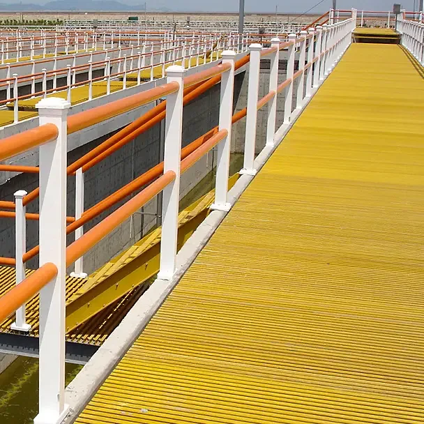
A support under only several bearing bars does not carry the complete panel. Show the structural support route and confirm that each load bar has effective bearing at the intended ends.
A clip may retain a panel without creating a bearing seat. A cross rod may touch a frame without turning into a bearing bar. A trim angle may close an edge without supporting the load path. Those details belong in the support description, not in a general “supported on four sides” note.
Read Load and Deflection as a Pair
Deflection alone is not enough. It needs the load at which it occurs, the span, the support condition and the limit used for acceptance.
A table may list a superimposed uniform load and a paired deflection at each span. That pair can be useful, but it does not become a point-load, wheel-load, impact or permanent-load rating. The load and span guide explains why those load patterns need separate treatment.
Check what kind of number the table publishes:
- a recommended load;
- an allowable or design load;
- a tested result under stated conditions;
- an ultimate capacity; or
- a maximum load associated with a serviceability criterion.
Those labels are not interchangeable. An ultimate value is not a normal working load unless the project method and safety basis explicitly convert it.
Match the Complete Product Row
Our pultruded schedule includes I, T and WT profiles with different depths, top widths, pitches, open areas and nominal mass. Equal nominal depth does not establish equivalent stiffness or capacity.
Record:
- profile family and exact section;
- depth, top width and web geometry;
- bearing-bar pitch;
- cross-rod spacing and assembly;
- resin and surface;
- panel direction;
- edge, opening and joint condition.
The I, T and WT section guide explains why a profile code or section modulus should not be ranked without comparing the complete panel.
Resin and exposure form a separate part of the same product identity. Use the pultruded resin-name resolution section when a structural comparison also depends on a named material system.
Avoid the “Same Thickness” Shortcut
Two panels can both be described as 38 mm. One may use an I profile, another a T profile with a wide top, and a third may differ in pitch or resin. Their open area, mass, local contact, assembly and applicable structural evidence can differ.
Thickness is useful for initial orientation. It is not enough to approve a span.
Compare Under the Same Support Condition
The same panel can be single-span, continuous over several supports, within a framed opening or supported only at its bearing-bar ends. Those conditions can produce different bending and deflection.
Four edge supports may be compatible with a pultruded panel when the design and detail provide the intended bearing. They do not make the two grid directions structurally equivalent. The bearing bars still need to follow the principal load path, and the evidence must cover the actual arrangement.
Openings introduce another support condition. A cut that removes bars can interrupt the intended span. Sealing the edge protects the laminate but does not rebuild the severed load path. Review the finished opening and support in the cutting and sealing guide.
Do Not Assume a Clip Transfers Load Across a Joint
A clip or connector may retain panels and keep adjacent edges aligned, but that does not automatically make two pieces act as one continuous structural member. A wheel, equipment foot or stored load near an open joint can be controlled by the local panel edge and fixing arrangement.
Show the load position relative to the panel ends, bearing bars, joint and clips. If the proposed panel is split rather than continuous, obtain evidence for that finished arrangement. Do not add the capacities of two separate pieces or assume that a clip turns a joint into a rigid beam connection.

Convert the Use into a Load Case
“Pedestrian walkway” describes an activity, not a structural load. Record the governing cases behind it.
For maintenance access, that may include a stated uniform live load and a concentrated tool or foot contact. For equipment, it may include operating weight delivered through defined feet or casters. For stored material, show the loaded area. For wheeled traffic, use individual wheel or axle loads, contact areas, route, turning and braking.
Do not divide a total equipment weight across an entire floor and call it uniform. The panel receives the load through its actual contacts. The heavy-duty grating guide develops those cases further.
Compare the Main Load Patterns
| Load pattern | Inputs that belong with the value | Common comparison mistake |
|---|---|---|
| Uniform area load | Pressure in kPa, kN/m², psf or lbf/ft²; loaded area; whether panel self-weight is included | Treating the pressure as the permitted weight of equipment or stored items |
| Concentrated line load | Force per unit length, line length and position across the bearing bars | Applying a uniform-load row to a narrow rail, skid or ladder load |
| Point or equipment-foot load | Force, contact length and width, position relative to bars and supports, duration | Entering only total equipment mass and omitting the loaded footprint |
| Wheel or moving load | Individual wheel or axle load, tyre or caster contact, route, turning, braking, frequency and impact | Dividing vehicle mass by the whole platform area |
The same total force can produce different local effects depending on the contact area and the bars that receive it. Use the load pattern named by the structural evidence rather than converting one pattern into another without a documented method.
Record Duration and Temperature
A load that remains in place is different from occasional access. A hot process area is different from ambient service. Dynamic, repeated or impact loading may also need a separate review.
The temperature and creep guide explains why a short-term ambient table may not cover permanent load or elevated temperature.
Set the Deflection Limit Before Looking at Values
The project needs an acceptance rule. It may be an absolute deflection, a fraction of span, a combination of both or a criterion contained in the governing standard.
Do not choose a product and then relax the limit to make a row pass. If the load and deflection pair fails, review the support spacing, section or alternative structural system.
Where a row is between published spans, do not interpolate or extrapolate unless the source explicitly permits it. A nearby row is evidence for its own printed conditions, not a universal formula.
Keep Metric and U.S. Inputs Traceable
Projects may provide a clear span in inches, a load in psf and deflection in inches while the supplier data uses millimetres and kPa. Record the original value, the converted value and the conversion used.
Useful dimensional conversions are:
1 in = 25.4 mm;1 ft = 0.3048 m;1 psf = 1 lbf/ft² ≈ 0.04788 kPa;1 kPa = 1 kN/m².
For example, a 48 in clear span converts to 1219.2 mm, not an assumed nominal 1200 mm. A 50 psf uniform load is about 2.394 kPa. These examples only normalize the input fields. They do not create a capacity result.
Example: Why Two Offers Are Not Yet Comparable
Suppose Offer A uses T38-33 at a measured 1000 mm clear span, and Offer B uses I38-60 at 1200 mm. Both tables show a 4 kPa uniform load and a 6 mm target.
The numbers look easy to compare, but the inputs do not. The profile, pitch, section geometry and span changed. The project may also use two end supports, while one offer’s data assumes a different bearing width.
The correct process is to:
- fix the measured span and support condition;
- fix the load pattern and deflection criterion;
- identify complete product rows that can fit those inputs;
- obtain matched values for each row;
- remove candidates that need a different spacing, support or service basis; and
- record the remaining approved configuration.
This example uses no unstated capacity value. It demonstrates why the form of the comparison matters.

Why Our Product Table Is Not a Load Table
The pultruded product page lists nominal profile dimensions, pitch, open area and mass per square metre. Those values help identify and price the product.
They do not approve a span. A mass value describes the product; a load value describes a structural case. A deeper profile can be a candidate for a demanding span, but it still needs matched evidence.
Our factory can review the requested section, bearing direction and finished-panel layout. We can identify when the drawing or requested product row is incomplete. Structural responsibility for the support, loads, deflection and final suitability remains with the project’s responsible designer.
This boundary is important. Manufacturing to a clear drawing is not the same as independently approving the building or platform design.
Compare Manufactured Panels, Not Only Catalog Bars
Our pultruded panels are made to the required width and bearing-bar length, with cutouts and edge details where specified. That means the delivered piece can differ from a generic full panel.
Before release, check:
- whether an opening interrupts bearing bars;
- how the remaining bar ends are supported;
- whether the panel is split for handling or transport;
- whether a joint creates an unsupported edge;
- whether clips or edge trim alter the support condition;
- whether piece orientation is controlled on the drawing.
The finished-panel check belongs beside the section table, not after fabrication.
What to Request From a Supplier
Ask for evidence that states:
- the exact section, depth and pitch;
- resin and surface when relevant;
- span definition and support arrangement;
- load pattern, value and units;
- paired deflection and its limit;
- allowable, design or ultimate basis;
- static or dynamic conditions, temperature and duration;
- interpolation or extrapolation rules;
- whether the result covers the finished panel and cutouts.
A report that names only “38 mm pultruded grating” does not answer those questions. Neither does a catalog page that displays a dimensions table beside an unrelated load chart.
Where the project adopts the ANSI/ACMA/FGMC FRP Composites Grating Manual, identify the edition, required table or method and tested configuration. Keep the governing project standard separate from a supplier’s marketing claim or a generic material value.
Common Comparison Errors
- comparing depth without section geometry;
- comparing panel length with clear span;
- using support-center distance for a clear-span table;
- reading load without deflection;
- treating ultimate capacity as a working load;
- applying a uniform-load row to a wheel or point load;
- transferring data between I, T and WT rows;
- treating a panel joint or clip as an assumed load-transfer point;
- ignoring resin, temperature or sustained duration;
- assuming a sealed cutout restores the load path; and
- approving a full panel while ordering a cut piece.
The Same-Duty Rule
The useful question is not “which pultruded grating has the highest number?” It is “which complete configuration has evidence for this span, support, load, deflection limit and finished-panel condition?”
Keep the project inputs fixed. Compare complete product rows. Record the evidence basis and the unresolved items. That produces a defensible span comparison instead of a thicker-looking guess.
Comparison sequence
From Measured Supports to an Approved Configuration
Freeze the project demand first, then compare complete products and evidence.
Record effective bearing faces, clear spans, bearing width, joints and free edges.
State the pattern, magnitude, units, location, contact area and duration for every governing load.
Identify the project limits and the meaning of the published value.
Link profile, depth, pitch, resin, surface and finished assembly to the evidence.
Keep the project inputs fixed and remove candidates that cannot produce matching evidence.
Put the accepted evidence, assumptions, drawing revision and responsibility into the order record.
Evidence boundary
What a Useful Span-and-Deflection Result Must Show
The record must connect the project duty to the exact configuration and stated acceptance basis.

Exact product identity
The evidence names the same section, depth, pitch, resin and finished-panel condition as the offer.
Span definition
Clear span, support centers and panel length are not treated as interchangeable.
Paired values
Load and deflection are read together at the same point and basis.
Working-load meaning
Recommended, design and ultimate values are reported separately rather than mixed.
Service scope
Static ambient data is not presented as approval for impact, sustained load or elevated temperature.
Project responsibility
The factory can review the configuration, while structural acceptance remains with the responsible project designer.
RFQ checklist
What to Send With a Pultruded Span Review
Include the support drawing, load cases, acceptance criteria and finished-piece scope.
- Support drawing — Plan and section showing support faces, clear span, bearing seats, joints, free edges and cutouts.
- Panel schedule — Profile, pitch, width, bearing-bar length, quantity and piece identity.
- Load statement — Uniform, point, line, wheel or equipment load with magnitude, units, contact and position.
- Deflection limit — Project criterion such as an absolute value, span fraction or governing standard requirement.
- Strength basis — Required allowable, design or tested criterion and how it is to be evidenced.
- Service conditions — Temperature, duration, chemical exposure, traffic frequency and any dynamic or impact case.
- Fabrication scope — Openings, interrupted bars, edge treatment, fixings, handling splits and marking requirements.
- Acceptance route — The document, calculation or test that the project will accept and who reviews it.
Request a review
Send Your Pultruded Grating Structural Duty
Upload the drawing and list unknown values explicitly so the comparison can stay honest.
- Clear span separated from panel length
- Every load case and contact position shown
- Evidence matched to the complete configuration
Pultruded Grating Span and Deflection Questions
How do I compare pultruded grating span and deflection correctly?
Is clear span the same as panel length?
Can a table for one 38 mm pultruded bar be used for another 38 mm bar?
Should I choose from the load or the deflection column?
Is an ultimate load suitable as a working load?
Does a paper load table cover wheel loads and impact?
What changes if a wheel or equipment foot sits near a panel joint?
Can cutouts be ignored if they are small?
Does a resin upgrade increase load capacity?
What if the load is permanent or the temperature is elevated?
Can the factory approve the structural design?
Can I send spans, loads and deflection requirements in inches and psf?
This content was prepared and reviewed by Dengtai Industry’s technical and production team using the project conditions, available product data and applicable documents. Limits that require design, testing or approval are identified in the content. Content last checked: