Pultruded grating drawing guide
Pultruded Grating Bearing-Bar Direction: Drawing and Piece Marks
The bearing-bar direction is the principal span direction. Mark it from fixed supports, then carry the same direction, piece ID, joint and opening information through fabrication, packing and installation.
Prepared by
Dengtai Industry
Published
·
Reviewed

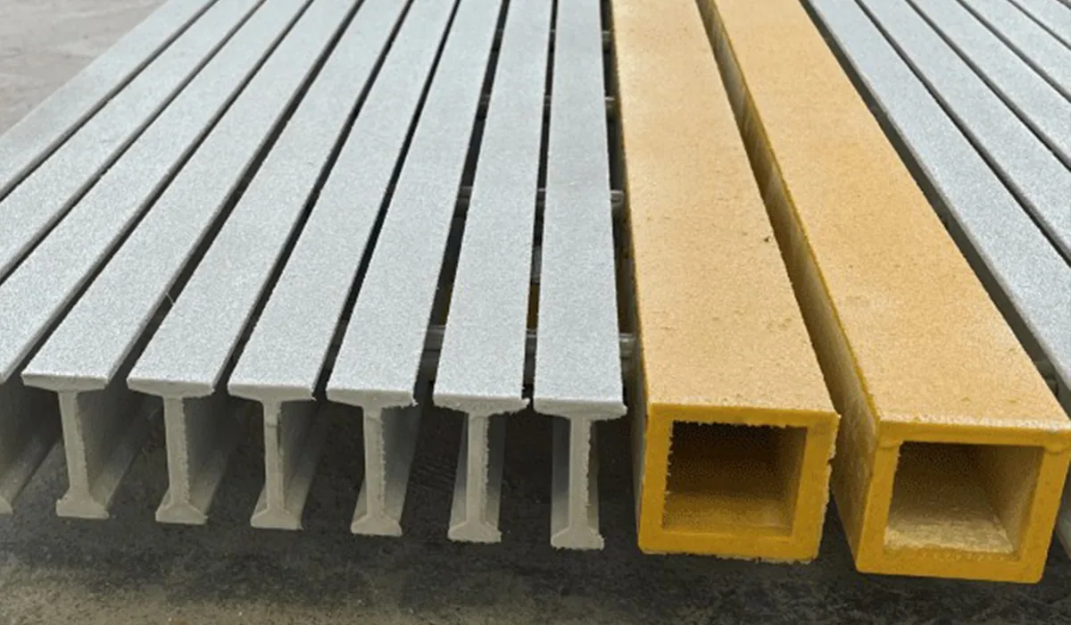
Parallel bearing bars define the main span direction. The transverse cross rods connect and stabilise them. Photo: Dengtai Industry.
Direction terms
Bearing Bars, Cross Rods and Piece Identity
The load path and the item identity must both survive the drawing and fabrication process.
- Bearing bar
- The continuous pultruded bar that carries the principal load along its length. In a pultruded grating panel, the bearing bars must run between the intended supports.
- Cross rod
- A transverse member that connects and stabilises the bearing bars. It should not be treated as a second equivalent spanning direction unless a specific design establishes that use.
- Bearing-bar length
- The overall direction and length of the bearing bars. It is also the direction in which the panel is intended to span between supports.
- Panel width
- The dimension across the bearing bars, commonly assembled with cross rods. Width and bearing-bar length cannot be interchanged merely because the panel fits an opening after rotation.
- Direction datum
- A fixed drawing reference from which the bar arrow and panel orientation are read. It may be a project grid, a building axis or a named support line.
- Piece mark
- The unique identifier for a panel or finished piece. It connects the physical item to its orientation arrow, cross-rod datum, openings, edge treatment and installation location.
- Rotation risk
- The possibility that a rectangular or nearly rectangular panel is installed with the bearing bars across the wrong supports because its outside dimensions still fit.
Drawing failures
What a Direction Drawing Must Prevent
A panel can fit an opening yet be structurally oriented in the wrong direction.
Swipe horizontally to view all columns.
| Drawing question | What the drawing must establish | What is not sufficient |
|---|---|---|
| Which direction spans? | A clear bearing-bar arrow connecting the two effective support lines. | “Horizontal,” “long side” or a photograph with no project datum. |
| Which elements carry load? | The bars running in the span direction are identified as bearing bars. | Cross bars that happen to align with the span are treated as equivalent. |
| Can a panel rotate? | Each unique piece shows orientation and required relationship to supports and joints. | Equal outside dimensions or a fit-check without the drawing. |
| Do cutouts change direction? | The opening, cut bearing bars, remaining ends and support are shown on the same plan. | A clean hole or sealed edge is assumed to preserve the load path. |
| Will the installer know the piece? | Piece mark and arrow survive fabrication, edge treatment, packing and delivery. | Loose notation on one sheet and unmarked panels in a bundle. |
Orientation review
When Bearing Direction Needs an Explicit Drawing Check
Increase the level of detail whenever panels can be rotated, handed or separated during fabrication.
Specify this if…
- Use a direction-marked drawing when two panels with equal outside dimensions can have different structural orientation.
- Use it when a walkway turns, branches or changes support direction.
- Use it when cutouts interrupt bearing bars or when pieces will be packed out of drawing order.
- Use it when field installation must be checked without comparing every panel to the full drawing.
Look elsewhere if…
- Do not accept “lay bars this way” as the only orientation instruction.
- Do not place the arrow horizontally on a rotating sheet without a project datum.
- Do not mark one panel and leave rotated or handed pieces unmarked.
- Do not treat the cross-rod direction as an equivalent span direction.
- Do not remove the piece mark before installing and checking the panel.
Drawing fields
Eight Marks That Keep Bearing Direction Traceable
Direction is useful only when it is connected to supports, piece identity and the approved revision.
Swipe horizontally to view all columns.
| Drawing field | Why it matters | Example entry |
|---|---|---|
| Project orientation | The arrow must survive page rotation and later drawing issues. | North arrow or grid reference; bearing direction set from it |
| Supports | Every bearing bar needs effective bearing at the intended start and end supports. | Show support faces, available bearing width and identify dead or non-bearing members |
| Clear span | The arrow identifies direction; the length still requires a measured span. | Dimension the unsupported distance along the bearing bars |
| Piece mark | The physical piece must be distinguishable from similar panels. | Unique mark on drawing, piece, inspection record and packing list |
| Top face | Surface and installation appearance may depend on a preferred top. | Mark top face where specified; do not infer from color alone |
| Joints and cross rods | Adjacent panels may require cross-rod alignment or a designed joint. | Cross-rod datum, joint location and required alignment |
| Openings | A cut can interrupt specific bearing bars. | Opening ID, dimension, position and affected bearing bars |
| Revision | A reissued drawing can change orientation without changing outside size. | Current revision, change cloud or revision note, release status |
On a pultruded grating drawing, the bearing-bar direction should be marked as the direction in which the parallel bearing bars travel between effective supports. It is the principal span direction, not just the longer side of the rectangle.
The drawing needs more than a generic arrow. It must tie the direction to a project datum and show where the bars bear, which pieces are rotated or handed, and how piece marks survive through fabrication and delivery.

Direction Is a Structural Field
A pultruded grating panel is assembled from parallel bearing bars and transverse cross rods. The bearing bars carry the principal load along their length. The I, T and WT bearing-bar section guide connects the chosen profile to support, load and evidence; the bar-spacing guide explains why cross-rod spacing and clear opening remain separate fields.
This means a rectangular panel can fit in two orientations while serving only one intended span. Cross rods connect the bars; they are not normally an equivalent second spanning direction.
Mark the Direction From a Fixed Datum
Place a project north arrow, grid line or named building axis on the drawing. Then show a separate arrow along the bearing bars.
The bar arrow should:
- begin and end near the effective support lines;
- run parallel to the bearing bars;
- have a clear label such as “bearing-bar direction — spans to supports”;
- appear on every rotated, handed or separately supported piece;
- remain readable when the sheet is rotated or exported.
“Horizontal bars” or “bars along the long side” can become wrong after a drawing rotation, a copied detail or a change in site orientation.
On a public accessible route, direction has a second check. The U.S. Access Board ADA guidance requires elongated floor openings to place their long dimension perpendicular to the dominant direction of travel, while limiting the narrow dimension. The applicable standard, product geometry and finished route still have to be confirmed; use the bar-spacing guide for that check rather than assuming a narrow-looking grid is compliant.
What Must Be Marked on the Drawing
Support Lines and Bearing Ends
Show the actual support positions and both bearing ends of the bars. Distinguish a bearing member from a trim angle, pipe support or panel connector that merely touches the edge.
The bearing direction says where the bars go. The clear-span dimension says how far they travel. Both belong on the same drawing.
Use the same span and support definitions as the applicable load evidence; the load and span guide explains the inputs that have to accompany a table value.
Four-Edge Support Does Not Erase Direction
A panel may sit within a frame that touches all four edges. That does not make its two grid directions structurally equivalent. The bearing bars still need to run as the primary load path from one effective support to the opposite support, and the drawing should say which edges are structural, which are framing or trim, and where the panel is fixed.
Where several oriented pieces, openings and support conditions form one operating deck, continue with the complete operating-platform planning guide to connect each piece to the platform boundary, equipment loads and agreed supply scope.
Side supports can limit edge movement or carry local details, but their presence does not turn cross rods into bearing bars. If the layout relies on four sides for a different structural reason, that assumption belongs in the project design and must be supported by evidence for the proposed panel.
Every Bearing Bar Needs Effective Bearing
A support line under only a few bars does not support the whole panel. Show the complete support route and confirm that every bearing bar at that end has an effective bearing surface. Contact through a cross rod, a loose trim angle or a clip alone is not a substitute for bearing under the load bars.
The required bearing width is project- and product-specific. Obtain it from the structural detail or the conditions attached to the load evidence; do not assume that touching the frame edge is enough or transfer one supplier’s minimum bearing dimension to another system. Check seat flatness, debris, packers, overlaps and the space needed for clips while the support is visible.
Panel Width and Bearing-Bar Length
Make the dimensions unambiguous:
- bearing-bar length: measured along the bars;
- panel width: measured across the bars and cross rods.
Do not rely on “length” and “width” if the schedule may be read without the drawing. A column heading such as “bearing-bar length” is more difficult to misread.
Piece Marks and Top Face
Every different panel should have a unique mark when its orientation, dimensions, openings, joints or support condition differ from another piece.
Include:
- piece ID;
- bearing-bar arrow;
- top-face requirement;
- cross-rod alignment or datum;
- opening IDs;
- quantity;
- drawing revision.
Equal outside dimensions are not enough to identify interchangeable pieces.
Cross-Rod Alignment and End Offsets
The bearing direction establishes the main span, but the cross rods create a separate datum along the bars. Two panels can have the same bearing-bar length and width yet place cross rods differently relative to the ends.
Where alignment matters, show:
- the end from which the cross-rod dimension is taken;
- any pair of panels whose cross rods must line up;
- the acceptable difference at the joint;
- whether a joint connector depends on that alignment;
- any lifting or fixing point tied to a cross rod.
A general note to “match existing panels” is weaker than naming the datum. A replacement panel may fit the frame but create a different local grid, fixing position or surface pattern.
Handle Turns, Branches and Corners
When a walkway changes direction, a single orientation cannot automatically continue around the corner.
Use a dedicated piece mark and show:
- the bearing-bar arrow on the corner piece;
- the bearing faces at both legs;
- the joint between panels;
- any change in support direction;
- the installation order;
- whether a separate structural element supports the turn.
The same care applies to a platform with pipe openings, a T-junction or a local equipment frame.
Example: Four Similar-Looking Pieces
An access platform may contain four rectangular panels whose outside sizes look similar:
- P01 is a standard field piece on two parallel supports;
- P02 is the same outline but spans between a beam and an edge frame;
- P03 is a corner piece with bearing bars turning onto the second walkway leg;
- P04 contains a pipe opening that interrupts two bearing bars.
The direction drawing should give each piece its own mark, arrow and support relationship. P04 also needs the opening ID, interrupted-bar information and added-support condition.
During packing, the four pieces may be separated from their drawing order. The marks and arrows must remain legible so the installer does not choose by outline. During replacement years later, the same drawing should make it possible to see that P01 and P02 were not interchangeable even if one could physically be placed in the other location.
Issue a Complete Drawing and Packing Package
The released package should use one piece identity across the layout, piece schedule, fabrication drawing, inspection record and packing list. At minimum, link each item to its location, bearing-bar arrow, dimensions, openings, edge treatment, quantities and current revision.
A drawing that shows only an unmarked outline leaves the factory to infer the project datum and leaves the installer to decide orientation by appearance. Before release, confirm that the latest drawing is the one used for fabrication and that every package label still matches it.
The pultruded packing guide explains how to keep direction and piece marks visible through bundle support, wrapping and loading. The receiving guide continues the same check at destination.
Show Bearings and Cuts on the Same Plan
A cutout or trimmed end can remove a bearing bar or reduce end bearing. Mark:
- which bars are interrupted;
- whether the remaining bar ends reach a support;
- any added frame or trimmer;
- the cut-edge treatment;
- the piece mark after fabrication.
The cutting and sealing guide explains the fabrication method. The drawing still determines where the cut bars must land.
For a pultruded-specific release check covering bearing-bar ends, cross-rod datum, cut-face quality and edge sealing, use the cut-end and cross-rod inspection guide.
Rotation and Replacement Panels
Replacement work is particularly prone to direction errors. Measure the support faces and identify the bar direction of the existing panel; do not copy only its outline.
If the new supplier cannot match the existing section, pitch or cross-rod layout, the panel may still “fit” but not be directly interchangeable. Record the difference and obtain approval before manufacture.
The quality and documentation guide explains how the replacement drawing, inspection record and certificate or report remain separate documents.
The replacement record should include:
- measured support faces;
- original bar direction;
- existing section and pitch;
- cross-rod datum;
- top surface and color;
- clipping or fastening detail;
- any opening and edge-treatment condition;
- the proposed product row and drawing revision.
If the existing direction cannot be determined, stop and review the support drawing. A panel that has already been installed in the wrong orientation is not a reliable template.
Packing, Delivery and Installation
The direction mark should remain connected through:
- nesting and fabrication;
- edge treatment;
- inspection;
- packing labels;
- installation drawing;
- final site checks.
At receiving, check the piece ID against the packing list and the arrow against the drawing. At installation, dry-lay the panel and verify that the bearing bars reach the intended supports.
If a bundle contains both handed and non-handed pieces, inspect the package before it is opened into loose stock. Keep the pack label until the piece marks and arrows have been checked. A temporary label that obscures the panel surface should be positioned so it does not prevent identification of the delivered piece.

Removable and Trench Panels
For covers, direction must also survive lifting and reinstallation. A removable panel that can be replaced backward is a direction-control problem, not only a maintenance convenience.
Show the direction on:
- the loose panel;
- the supporting frame;
- the installation drawing;
- the inspection record.
If the cover is symmetrical in outline but directional in the bearing bars, add a permanent or durable mark that will not be lost during cleaning.
Common Drawing Errors
- Writing only “lay bars horizontally.”
- Using panel length or the longer side as the direction instruction.
- Treating the cross-rod direction as equivalent.
- Marking the bar direction without the supports.
- Showing supports without the clear span.
- Giving one direction arrow to every piece in a rotated bundle.
- Omitting top-face or cross-rod alignment requirements.
- Reusing an old drawing after moving or changing a support.
Release the Direction With the Revision
The bearing direction is only controlled when it belongs to the released drawing. If the support layout, panel split, top face or opening changes, issue a new revision and identify which pieces are affected.
Do not send a field message that changes the arrow while leaving the original piece marks and packing list in use. The factory, inspector and installer need one controlled direction for each item.
The pultruded selection guide covers the wider sequence from supports and load evidence to section, material and fixed panel schedule.
The Manufacturer Rule for Bearing Direction
Establish a fixed datum, draw the bearing-bar arrow between the effective supports and mark every unique piece. Carry the direction and piece identity through fabrication, packing and site fit.
If the direction cannot be checked on the delivered item, the drawing is not yet a complete manufacturing instruction.
Drawing sequence
From Project Datum to a Marked Piece
Establish direction, add local geometry, then carry the identifier through delivery.
Tie the drawing to a grid, building axis or named frame reference.
Mark the support faces and the direction the bearing bars must travel.
Add orientation arrows and piece IDs to handed, rotated or separately supported panels.
Show cross-rod alignment, openings and the support changes caused by cuts.
Keep the arrow, top face and revision through cutting and edge treatment.
Check piece marks and package labels before installation.
Factory boundary
What the Drawing and Factory Can Confirm
We can fabricate to a clear layout, but cannot infer the supporting direction from an unmarked outline.

Direction from a datum
The bar arrow is tied to a project grid, axis or named support reference rather than page orientation.
Supports included
Both effective bearing faces are shown so the arrow can be checked against the intended load path.
Unique pieces identified
Rotated, handed or separately supported panels receive their own piece marks and orientation instructions.
Cutouts connected
Openings and interrupted bearing bars appear on the same drawing as the support arrangement.
Marks survive fabrication
The piece ID and direction remain traceable through cutting, inspection, packing and delivery.
Responsibility clear
The factory fabricates the marked geometry; the project designer confirms the support and structural direction.
RFQ checklist
What to Send With the Pultruded Direction Drawing
Send the support plan, direction datum and piece schedule together.
- Support plan — Support faces, available bearing width, clear spans and any structural frame change.
- Project datum — North arrow, grid line, building axis or other fixed reference for direction.
- Panel schedule — Bearing-bar length, width, quantity, piece marks and handing requirements.
- Joint detail — Required panel relationships and cross-rod alignment where applicable.
- Opening drawing — Cutouts, notches, interrupted bars and support around each opening.
- Top-face requirement — Any defined walking face, surface direction or appearance requirement.
- Marking method — How piece identity and direction will remain visible without damaging the panel.
- Drawing revision — The exact approved issue used for fabrication and site fit.
Request a review
Send Your Pultruded Grating Layout
Upload the marked drawing and identify any panel that can be rotated or confused with a similar piece.
- Bearing-bar arrow tied to a project datum
- Rotated and handed pieces individually marked
- Cutouts and piece IDs on the same revision
Pultruded Grating Bearing-Direction Questions
Which direction is the bearing-bar direction on pultruded grating?
Are cross rods a second bearing direction?
Why is “lay bars horizontally” not enough?
Do identical-looking panels need piece marks?
How should a rotated walkway section be marked?
Can a cutout change the bearing direction?
Should the direction mark stay after installation?
Must every bearing bar sit on a support?
This content was prepared and reviewed by Dengtai Industry’s technical and production team using the project conditions, available product data and applicable documents. Limits that require design, testing or approval are identified in the content. Content last checked: