Engineering selection guide
Pultruded FRP Grating: How to Choose I, T & WT Bars
Begin with the supports and the load path, not a product code. This guide turns a platform or walkway drawing into a defensible choice of bearing-bar direction, section, pitch, material, finish and fabricable panel schedule.

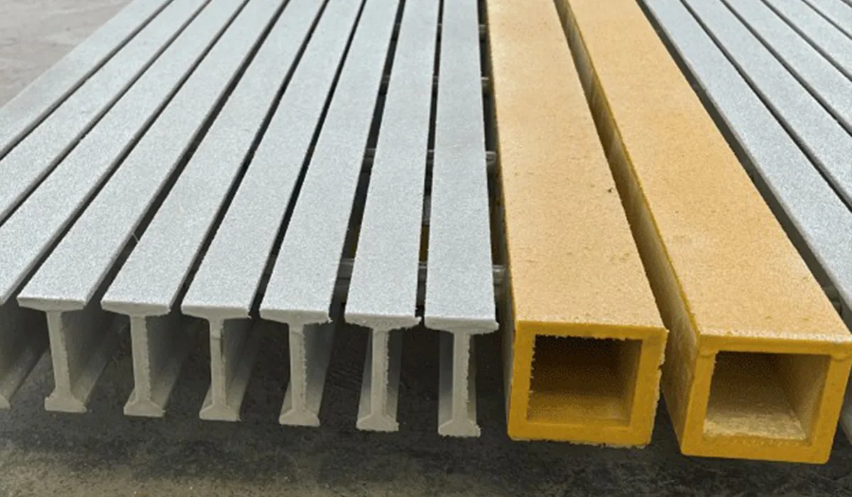
Bearing bars and cross rods are visible in these factory samples. Photo: Dengtai Industry.
Selection matrix
Pultruded FRP Grating Selection Questions
Use the six questions below to expose the inputs that can change the selection. A provisional direction is useful; a confirmed specification needs evidence for the exact panel.
Swipe horizontally to view all columns.
| Decision | Ask first | Evidence that closes the choice |
|---|---|---|
| Is pultruded grating a candidate? | Do the supports create a clear span along one dominant direction? | Marked support drawing showing where both ends of every bearing bar land. |
| Which bar family should be compared? | Does the load enter through a narrow contact, along a broad top flange, or through a dense traffic area? | I, T and WT geometry shown with pitch, clear opening and the actual load direction. |
| Is the clear span acceptable? | What are the load case, bearing width and permitted deflection for this exact panel? | Configuration-specific calculation or test evidence for the same section, resin and support condition. |
| Will cutouts alter the structure? | Which bearing bars disappear, and where will their cut ends be supported? | Opening layout overlaid on the bar schedule, plus an agreed perimeter-support detail. |
| What belongs in the material specification? | Which chemical, temperature, fire, UV or electrical condition must be evidenced? | Resin direction, surface finish and documents checked against the finished configuration. |
| Can the delivered panels be identified? | Could two pieces with identical outside dimensions still have a different function? | Piece marks, bar direction, cross-rod datums, revision and packing list tied to one drawing. |
Suitability screen
When Pultruded FRP Grating Is the Right Starting Point
Pultruded grating is most useful when the structure gives it a clear directional load path. The warning signs below do not make it impossible to use, but they must be resolved before a panel is ordered.
Specify this if…
- The structural frame clearly creates one main spanning direction, and the bearing bars can run continuously from one effective support to the opposite support.
- A long clear span, a deeper directional section or a lower panel mass is being considered against the actual supports and the same load case.
- The project can define finished panel widths and bearing-bar lengths before fabrication, allowing the panel schedule to follow the layout instead of forcing a fixed sheet into it.
- The environment, surface and fixing requirements can be evidenced for the proposed finished assembly, not merely inferred from the letters “FRP”.
- The buyer is prepared to review bar direction, openings, joint positions and piece identity during quotation rather than compare only a price per square metre.
Look elsewhere if…
- The support direction is still unknown, and the team is using panel thickness as a substitute for a structural layout.
- The requested dimensions come only from an old panel, while the existing support faces and clear spans have not been measured.
- Large openings remove bearing bars, but nobody has defined how the remaining bar ends and opening perimeter will be supported.
- The specification requires a performance class, but the project has not identified the test method, acceptance value or the finished configuration covered by its evidence.
- The main requirement is a highly cut-up, multi-directional layout on a closely framed opening that has not yet been compared with molded grating.
Structure comparison
Pultruded FRP Grating vs Molded Grating
Compare the structures at the decision level first. The product family narrows the review; the finished configuration and support condition decide whether it is suitable.
Swipe horizontally to view all columns.
| Selection issue | Pultruded FRP grating | When molded deserves equal review |
|---|---|---|
| Load path | Parallel pultruded bearing bars form the principal spanning members; cross rods connect and stabilise the assembly. | An integral molded grid can distribute load in two directions and often suits a framed opening with less dominant span direction. |
| Layout change | Rotating a panel changes which supports the bearing bars reach, so orientation is part of the product definition. | A square or rectangular grid may offer more tolerance to a changing layout, but the finished frame, cutouts and deflection still require review. |
| Openings | Cutting a bearing bar interrupts the principal load path; the remaining end needs a deliberate support condition. | Cutting the mesh also removes material, but the remaining distribution path can make an irregular framed opening easier to arrange. |
| Custom geometry | Panels can be planned around an ordered width and bearing-bar length, with piece-level fabrication and orientation. | Standard molded panels may offer fewer piece-specific variables, although factory cutting and panel dimensions still affect yield. |
| Comparison trap | “Pultruded” does not prove strength. The section, pitch, resin, support, span, load and deflection must belong to one dataset. | “Molded” does not prove economy or two-way capacity for every cut layout. Compare the delivered scope and the actual structural data. |
RFQ configuration summary
Pultruded FRP Grating Configuration Summary
Use this as the compact specification checklist. The product page carries the detailed I, T and WT series schedule; this summary keeps the selection inputs together before quotation.
Send the Configuration for Review| Specification | Value |
|---|---|
| Bearing direction | One marked span direction Show both support faces and confirm that every bearing bar can reach support at each end. |
| Bar family | I, T or WT candidate Compare the actual profile, not the nominal depth alone, against the load location and available installation depth. |
| Opening geometry | Pitch plus clear opening Open-area percentage does not describe the gap seen by a wheel, foot, tool or dropped object. |
| Service build | Resin, colour and surface Match the resin and finish to the chemical, temperature, UV, cleaning and traffic conditions. |
| Retention | Clip type and fastener material Confirm panel height, bar width, support geometry, exposure and whether the panel is removable. |
| Fabrication | Width × bearing-bar length Include joint positions, openings, cross-rod datums, edge treatment and piece marks on the drawing. |
What This Pultruded Grating Guide Decides
Pultruded FRP grating is assembled from parallel glass-fibre-reinforced bearing bars and cross rods. That construction has a direction. The useful selection question is therefore not simply “which pultruded panel is strongest?” It is “which bearing-bar layout reaches the real supports, survives the real load case and can be manufactured and installed without ambiguity?”
This guide is for engineers, fabricators, procurement teams and asset owners who already have a platform, walkway, cover or equipment-access layout and need to convert it into a candidate specification. Use our I, T and WT bearing-bar section guide to compare the actual profiles, then return here for the full selection sequence. This page concentrates on the decisions that come before and around a quotation.
Start with
Supports and clear span
Define where load can reach a bearing surface before comparing sections.
Then test
Section, pitch and evidence
Keep the geometry, load direction and supporting document in one configuration.
Finally release
Fabricable piece schedule
Make every panel traceable by orientation, openings, fixings and drawing revision.
Read the Product by Its Load Path
The bearing bars are the principal spanning members. They need an effective bearing or connection at each end. Cross rods hold the bars at spacing, transfer local effects and keep the assembly together, but they do not turn the product into a bidirectional molded grid. When a rectangular panel is rotated, its outside dimensions may still fit while its internal load path no longer matches the frame.
Once the support route is known, use the pultruded bearing-bar direction guide to turn it into a marked per-piece layout. Use the bar spacing and open area guide when the pitch, clear opening, wheel path or accessibility criterion also governs the product row.
This distinction affects every later decision. A deeper bar may be appropriate because the clear span and deflection limit demand it, or a smaller section may be sufficient because the supports are close together. Neither answer can be selected from a photograph of the walking surface. Inspect the underside, the supporting steelwork and the panel ends together.
When offers use different sections or spans, use the pultruded span and deflection comparison to rebuild the same-duty record before comparing the results.
Match the Project Task to a Pultruded Grating Shortlist
A product task helps narrow the review, but the task name is not a specification. Use the table to identify the first questions to ask, then confirm the support layout, load and exposure for the actual piece.
| Project task | Why pultruded grating may be compared | What usually controls the decision | Continue with |
|---|---|---|---|
| Industrial walkway or catwalk | Long, directional runs can follow beams that already create a clear span | Clear span, traffic, deflection, joints, edge protection and fixing access | FRP walkway planning and catwalk requirements |
| Equipment platform or service floor | Concentrated equipment feet and long one-way framing may suit directional bars | Load position, transfer beams, openings, vibration and removal of equipment | GRP flooring selection |
| Trench, channel or removable cover | Bars can span across a defined opening and the panel can be divided into liftable pieces | Support seats, lifting, point or wheel load, movement and whether the cover is pedestrian-only | FRP trench-cover planning |
| Chemical or wastewater access | A pultruded panel may fit the structure while resin and surface are selected for the process exposure | Medium, concentration, temperature, splash or immersion, cleaning and available evidence | Wastewater grating guidance and chemical-resistance review |
| Coastal or marine platform | Corrosion-resistant grating can be considered where salt and wash-down make steel maintenance difficult | Resin, UV, clip grade, galvanic detail, wind or uplift and inspection access | Offshore and marine platforms and dock walkways |
| Solar maintenance route | Long straight rails may align with directional bearing bars | Rail spacing, module gaps, maintenance load, walk width and fixing detail | Solar walkway planning |
| Public or shared-access route | Open grating can offer drainage, but public use adds requirements beyond the panel | Finished clear opening, wet grip, guardrails, transitions and project accessibility criteria | FRP grating standards and evidence |
| Replacement on an existing frame | The available support direction may favor a made-to-order directional panel | Measured clear spans, bearing condition, old-panel orientation, clip rows and piece identity | FRP grating installation planning |
The same task can lead to a different result when the structure changes. A long walkway over closely spaced cross-beams may not need the deepest available bar, while a short equipment platform may still need a deeper section because a concentrated load lands between supports. Use these routes to ask a better question, not to assign a section from the application name.
How Pultrusion Creates a Directional Grating Panel
Pultrusion explains why pultruded grating behaves differently from an integrally molded grid. Continuous glass reinforcement is pulled through a resin system and a heated die, producing a constant-profile bearing bar with its principal reinforcement running along the bar. Those I, T or WT bars are then assembled with cross rods into the open panel.
The manufacturing sequence connects directly to the selection checks:
- Reinforcement and resin form the bar. The resin direction is chosen for the service environment, while the continuous reinforcement supplies the longitudinal structure.
- The heated die sets the profile. Bar height, flange shape and web geometry belong to the section that must be matched to the load and available depth.
- Bars are assembled with cross rods. Cross-rod spacing and end positions complete the panel construction and must be retained in the piece definition.
- The panel is finished to the order. Width, bearing-bar length, openings, edge treatment and piece marks turn the assembled structure into an identifiable delivered part.
That is why a pultruded panel has a principal direction and why its production history matters to procurement. A photograph of the top surface may show a walking finish, but it does not show the bar section, cross-rod datum, end bearing or finished piece identity.
Decision 1: Read the Support Drawing Before the Catalogue
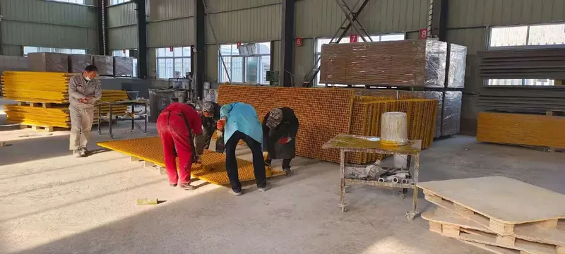
The first drawing should answer a physical question: where can the bearing bars be supported? Mark beams, purlins, cleats, frame members, existing seats and every interruption. Distinguish a bearing member from a trim or retaining angle that merely touches the panel edge.
For each span, define:
- the bearing-bar direction;
- the clear unsupported distance between bearing faces;
- the width available at each end for seating or connection;
- support elevations and any packing or levelling detail;
- panel joints, gaps and the sequence of installation; and
- any opening that removes or interrupts a bearing bar.
Do not start with the outside dimensions of a supplied sheet. A frame can have an overall opening of 1,500 mm while the structural clear span is smaller because of seat plates, insulation, a drainage lip or transfer members. A previous panel can have a 1,500 mm length while only part of that length bears on steel. Those are different structural conditions.
For the finished-piece mass behind the handling and support decision, use the pultruded grating weight guide with the exact profile row rather than a generic depth.
Mark Rotation and Joints on the Same Drawing
Place a north arrow or project datum on the drawing, then mark the bearing direction relative to it. This is more reliable than writing “horizontal bars” when the sheet may be rotated during printing, issue or fabrication. Number each panel and show any required alignment of cross rods between adjacent pieces.
If a walkway changes direction, do not assume one panel orientation works for both legs. A corner may require a dedicated piece, a change in support direction or a different product construction. Resolve that geometry on the drawing before splitting the order into rectangles.
Decision 2: Turn the Use Case into a Load Case
“Pedestrian walkway” describes the activity, not a structural load. Define who and what reaches the panel, then express the condition in a form that can be checked. Common starting points include a distributed maintenance load, a concentrated foot or equipment contact, a wheel load, stored material, temporary construction activity and a sustained load from equipment left in place.
For each load case, record the value and units, contact area or distribution, position on the panel, direction of travel or force, duration and any simultaneous environmental effect. A trolley is not represented by dividing its total mass by the whole platform area. The wheel contact, wheel spacing, route and local support condition matter.
| Use condition | Inputs to resolve | Why the selection can change |
|---|---|---|
| Maintenance access | Distributed load, tool or equipment contact, access frequency and work below | A nominal walking load may not cover concentrated tools or temporary equipment |
| Trolley route | Loaded wheel force, wheel width, spacing, turning area and contact surface | Wheel contact and local bar spacing can govern before an average area load does |
| Equipment platform | Footprint, fixing points, operating mass, vibration and duration | The load may arrive through a few pads rather than uniformly across the grating |
| Removable cover | Lifting points, impact during handling, support seats and wheel or foot traffic | The panel must be structurally suitable both in service and during removal |
| Long-term installation | Sustained force, temperature, creep and maintenance access | A short-term strength check may not describe long-term deflection |
Define Deflection as an Acceptance Criterion
The permitted deflection belongs to the project requirement, not to a convenient table. It may come from an engineering limit, the sensitivity of adjacent equipment, drainage, a doorway level, human comfort, appearance or the movement allowed at a support detail. State whether the limit is an absolute value or related to span.
Check that the chosen evidence uses the same definition of span, support and load. A test or calculation described only as “600 mm span” may not state whether it refers to clear distance, centre-to-centre spacing or test-rig geometry. If the basis is unclear, the number is not yet a specification.
Decision 3: Choose I, T or WT by Where the Load Enters
I, T and wide-top T are different ways of placing material in a pultruded bearing bar. Their names do not create a universal ranking. The useful comparison combines profile dimensions, pitch, clear opening, walking surface, load position, local contact and assembly details.
An I-profile places flanges at both the top and bottom of the bar. A T-profile places a flange at the top with a stem below. A wide-top T changes the top flange geometry again. Whether that difference helps depends on the actual contact and the connection to cross rods, as well as the structural section properties and the support condition.
Our practical sequence is:
- Confirm that a directional bearing-bar product is structurally appropriate.
- Compare the available profiles at the actual clear span and load case.
- Check the clear opening and traffic requirements with pitch and surface.
- Confirm the manufacturing and fixing details for the selected assembly.
- Obtain project evidence for the resulting configuration.
The product page lists our nominal I, T and WT series. Use those dimensions to form candidates, then ask for the matching design or test basis. Do not choose a thinner bar because the open area is attractive, or a deeper bar because it looks more robust, without checking deflection and installation depth.
Decision 4: Separate Pitch, Open Area and Clear Opening
Three measurements are often mixed together during procurement:
- Bar pitch is the repeat distance between adjacent bearing bars, commonly measured centre to centre.
- Open area is the proportion of the overall panel that is open.
- Clear opening is the actual unobstructed gap a foot, wheel, tool or object sees between finished edges.
Two panels can show a similar open-area percentage but have different clear opening shapes. Open area is useful for drainage, ventilation and general comparison. It does not answer whether a small wheel can cross safely, whether a dropped item will pass below or whether a particular footwear requirement is met.
Add the walk direction, traffic, cleaning method and objects below the platform to the panel review. At a junction, the effective opening may be affected by edge bars, clips, covered sections or a change in panel orientation. Check the finished detail rather than the catalogue pattern in isolation.
Use Samples for Contact, Not as a Rating
A sample can reveal the shape of the top flange, the tightness of a cross-rod connection and the feel of a textured surface. It cannot establish the allowable load of every panel built from the same profile. Keep appearance and touch assessment separate from engineering verification and final acceptance documentation.
Decision 5: Match Resin, Surface and Fixings to Service
FRP is a material family, not a complete specification. The resin, grade, reinforcement, surface and final geometry all belong to the product description. Start with the actual medium, concentration, temperature, splash or immersion pattern, cleaning practice, UV exposure and any fire, smoke, static or electrical requirement.
Polyester, vinyl ester, phenolic and epoxy are directions for different project discussions. A resin name alone does not prove compatibility with a chemical or establish a fire class. Our recommendation is to send the service conditions and the required acceptance method so the proposed configuration can be checked with supporting information.
Surface and fixing decisions continue the same assembly logic:
- choose the walking texture against wetness, contamination, footwear, wheels and cleaning;
- confirm the resin, colour and UV expectation together;
- select clips for panel height, bar width and support geometry;
- use stainless or galvanised fasteners only after checking the exposure and galvanic condition;
- distinguish clips that retain the panel from supports that carry it; and
- define removable panels, lifting points and access before fixing the piece split.
Use the resin selection guide and surface and treatment guide to develop the detailed inputs. The clip selection guide is the place to resolve retention hardware.
Why Two Equal-Sized Pultruded Panels May Not Be Interchangeable
An outside width and length do not fully describe a pultruded panel. The internal definition also includes:
- which direction the bearing bars run;
- whether the panel can be turned over;
- the position of cross rods from each end;
- the number and location of cut bars;
- the support around each opening;
- edge-sealing treatment;
- clip positions and removable-panel details; and
- the piece mark and drawing revision.
A replacement panel can fit the measured rectangle and still concentrate load on the wrong support or prevent the clip rows from lining up. It may also obstruct a pipe because a cross rod occupies a slightly different position. The safest route is to re-measure the supported layout and recreate the piece definition, using the old panel only as a cross-check.
| Same-looking feature | Hidden variable that can change function |
|---|---|
| Equal length and width | Bearing bars may run in different directions |
| Equal bar spacing | Cross-rod positions or end offsets may differ |
| Similar opening dimensions | The opening may cut a different number of bearing bars |
| Similar number of clips | Fastener spacing, support type or removable detail may differ |
| Same resin description | Grade, formulation, surface or evidence scope may differ |
Illustrative Drawing Review
Consider two panels with the same 1,200 × 2,000 mm outline. On panel A, the bearing bars run across a 1,200 mm clear span. On panel B, the same outline has been rotated, so those bars would need to span 2,000 mm between a different pair of supports. The panel may still fit the opening, but the load path has changed.
The review then adds the details that a simple outline hides. Does an opening cut three bearing bars or only a cross rod? Do the bar ends at the opening need a frame? Must the cross rods align with an existing clip row? Which marks distinguish panel A from panel B in production and packing? Those answers belong on the same drawing revision as the dimensions.
Where Custom Bearing-Bar Length and Panel Width Help
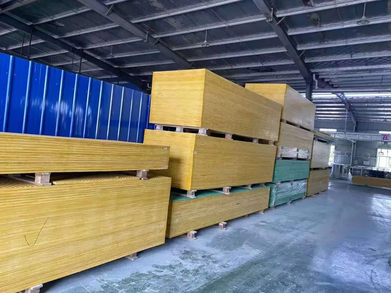
We manufacture pultruded panels to project dimensions rather than treating one fixed sheet as the only starting point. The advantage is most credible when the ordered panel follows the layout: define the bearing-bar length from the support geometry and the cross-bar width from the installation width, then account for edge details, joints and handling.
This can reduce the difference between purchased rectangular area and the area that ends up installed. It does not mean every custom order is automatically cheaper. Cutting, openings, edge treatment, clips, packing and transport still have costs, and a very small or awkward piece may be more practical to produce from a planned larger panel.
Compare Waste and Fabrication on the Same Scope
For each option, estimate:
- ordered panel or stock-sheet area;
- finished installed area;
- area removed by openings and edge trim;
- cutting and edge-sealing operations;
- handling splits and packing;
- site fitting and rejected pieces; and
- the supporting frame required in each case.
A custom panel that removes a major support may save steel and installation but require a deeper section and larger lifting plan. A standard-sheet approach may look cheaper at the material line but create more cutting, closure details and site labour. The comparison needs the whole delivered system, not a square-metre quotation in isolation.
The pultruded grating quote comparison guide provides the line-by-line scope for comparing those complete offers.
Six Procurement Failures to Catch Before Release
1. Selecting by depth alone
A 38 mm pultruded bar and a 38 mm molded panel are not equivalent just because the nominal depth matches. Section shape, pitch, load direction, support and evidence must align.
2. Treating four-edge support as a substitute for bar direction
A four-sided frame can contain a valid pultruded panel, but each bearing bar still needs an effective path between opposing supports. A frame around all four sides does not make the cross rods a second main span.
3. Ignoring the support under a cutout
An opening may remove one or several bearing bars. A clean cut edge and a sealed surface do not restore the interrupted span. Mark the remaining bar ends and the new support or frame on the drawing.
4. Using an unrelated load table
A span table is useful only when its section, pitch, material, support condition, load definition and deflection limit match the proposed panel. A product-family comparison cannot replace project-specific evidence.
5. Mixing open area with clear opening
Open area is a ratio. Clear opening is the actual gap. The choice for wheel traffic, dropped objects, footwear or cleaning depends on the finished opening, not only a single percentage.
6. Issuing visually similar pieces without marks
When several panels have the same outline, orientation and opening differences are easy to lose in fabrication, packing and installation. Give every variant a mark that appears on the drawing, label and packing list.
Audit the Load Data Before Accepting a Span
The strongest-looking document can still be unusable if it describes a different product. Before placing a load value in a quotation or on a drawing, check the following:
- Is the bar profile identified by more than its nominal depth?
- Are pitch, resin and relevant reinforcement described?
- Is the bearing-bar direction shown?
- Is clear span defined, and does the reference use the same definition?
- Is the support condition the same, including end bearing and any four-edge frame?
- Is the load type, magnitude, contact area and position stated?
- Does the permitted deflection meet the project requirement?
- Are temperature, duration and environmental effects within the stated range?
- Is the source a test, calculation or generic guide, and what does it actually cover?
- Does the evidence cover the finished panel with its openings and joints, or only an uncut specimen?
If any answer is missing, record it as an open item. The appropriate action is not to fill the gap with a more optimistic number. Use the standards and evidence guide and quality documentation guide to organize the final check.
The Manufacturer View: Design the Drawing, Not Just the Panel
Our workshop view is simple: a pultruded panel is only as clear as the drawing that defines it. The most useful early conversation is therefore not “what is your best price per square metre?” but “show us where the bars bear, what crosses the panel and how the pieces are identified.”
That conversation often exposes a revised support detail before it becomes a fabrication issue. Sometimes the answer is a different bar profile. Sometimes it is a dedicated edge or a frame around an opening. Sometimes the better product is molded grating. Making that decision explicit is more valuable than forcing every layout into one construction.
We also recommend that customisation be tied to a controlled dimension rather than cosmetic variation. A changed cross-rod position should have a purpose such as clip coordination, an opening or a joint. A different colour or surface should follow the exposure and traffic requirement. Every added variation needs a corresponding line in the drawing, production record and packing list.
Our quotation and factory review uses the same short set of controls before a panel is released:
- the bearing-bar direction agrees with the support drawing;
- the section, pitch and required evidence belong to the same configuration;
- cross-rod positions, end bearing, openings and fixings can be manufactured as drawn; and
- the piece mark on the drawing matches inspection and packing.
These are not decorative checks. They are the points that keep a technically suitable proposal from becoming the wrong installed piece. Review our factory production scope, the quality-documentation requirements and the cutting and sealing limits when those items affect the order.
Prepare a Quotation-Ready Pultruded Grating Package
The final selection package should let a reviewer reproduce the reasoning without needing a phone conversation. Include the support drawing, panel schedule, load statement, exposure notes, fixing requirement, destination and documents required for acceptance.
At minimum, give each panel a mark and state its width, bearing-bar length, quantity, bearing direction and orientation. Add the cross-rod datum, opening coordinates, edge treatment and fixing layout where these control fit. If a dimension is still unknown, mark it clearly rather than leaving a blank that can be mistaken for confirmation.
The cutting and sealing guide covers fabrication details, while the molded vs pultruded comparison helps when the structural family itself is unresolved. For help turning the drawing into a candidate configuration, use the selection form below.
Drawing and data audit
Pultruded FRP Grating Drawing and Data Checks
These checks catch the errors that are expensive to discover after fabrication, when a dimension looks right but the panel still reaches the wrong support or breaks the intended load path.
- Freeze the bearing direction — Draw one arrow along the bearing bars and confirm that it follows the intended span. A note saying “lay bars this way” is weaker than marking the bar direction on every different piece, especially when adjacent panels are rotated. Compare pultruded and molded load directions
- Measure clear span, not frame size — Record the unsupported distance between bearing faces, the seating width at each end and any gap or joint. Outside frame dimensions and purchased panel length can both be larger than the structural span, which makes a copied load-table row ambiguous.
- Treat cut bars as a structural change — Overlay every pipe, duct, ladder and access opening on the bearing-bar schedule. Identify cut bars, remaining bar ends, perimeter support and edge sealing. Sealing protects the cut laminate; it does not restore a severed spanning member. Review cut-edge and opening planning
- Separate panel retention from support — Clips hold the grating down and restrain movement. They are not substitutes for bearing seats. Confirm clip family, fastener material, support geometry, panel height and whether the panel must be removable. Check clip and fixing selection
- Audit the source of every load figure — Match section, pitch, bearing-bar direction, resin, support condition and span definition. If the evidence does not identify the tested or calculated configuration, obtain a qualified project review instead of applying the number to the quotation. Review technical documentation scope
- Control drawing revision and piece identity — Give every different panel a mark. Record width, bearing-bar length, bar direction, cross-rod datum, openings, edge treatment and quantity. A later change to one opening or end offset can make a visually similar piece non-interchangeable.
Release checklist
Pultruded Grating RFQ Release Checklist
Use this after the engineering method above. It verifies that the drawing, load evidence, material schedule and piece list are ready to become a comparable quotation.
Open the current drawing and confirm that the arrow follows the intended span on every rotated or differently supported piece.
Reconcile the support survey with the load statement. Mark any unresolved span, bearing width or deflection limit before asking for a final price.
Verify that the profile, pitch, resin and support condition in the load source are the same ones proposed for the order.
Record resin, colour, surface, clip family, fastener material, edge treatment and removable-panel requirements.
Issue the marked panel schedule with dimensions, quantities, bar orientation, openings, fabrication and the exact revision used for quotation.
Manufacturer review
Turn Your Drawing into a Pultruded Grating Quotation
A marked drawing is more useful than a guessed product code. Send the support layout, panel schedule and what you know about the load, exposure and fixing condition.
- We review support direction before recommending a section
- Cutouts, cross-rod datums and piece marks can be checked together
- Attach a drawing; unresolved inputs can be listed before quotation
Pultruded FRP Grating Selection FAQs
How do I start selecting pultruded FRP grating?
Is an I-bar always better than a T-bar?
Does higher open area mean better drainage?
Can I reuse a previous pultruded panel as a template?
Does custom panel width always reduce waste?
Can cross rods carry the main load if the panel is turned?
What happens if the load data does not match my panel?
When should I compare molded grating instead?
This content was prepared and reviewed by Dengtai Industry’s technical and production team using the project conditions, available product data and applicable documents. Limits that require design, testing or approval are identified in the content. Content last checked: