Installation guide
How to Install FRP Grating, Step by Step
Install FRP (fiberglass-reinforced plastic) grating by checking the supports, dry-laying the panels, cutting and sealing the edges, then fixing them with clips matched to the panel and the support. The steps below follow the order a site team actually works in, and show where the approved drawing, not a generic rule, decides the number.

Installed walkway on steel supports. Photo: Dengtai Industry.
Quick answer
What FRP Grating Installation Involves
Install FRP grating in this order: verify the supports, dry-lay the panels, cut and seal the edges, place the panels on their bearing surfaces, fit the hold-down clips and panel connectors, support the openings, then inspect and record the finished work. The sequence matters because a fixing cannot correct an unsupported panel.
- FRP grating panel
- A composite walking surface made from glass reinforcement set in resin. Molded panels are cast as one grid. Pultruded panels are assembled from continuous bearing bars and cross rods. Both arrive as flat pieces that have to be supported, restrained and protected at cut edges.
- Bearing bar or bearing edge
- The part of the grating that transfers load into the support. On a pultruded panel the main bearing bars run in one direction. On a molded panel the grid is one piece, but the panel still has to sit on the support at the positions shown on the layout.
- Clear span
- The unsupported distance between the edges of two supports. It is not the same as the distance between beam centres, because the beam centre distance includes the width of the supports.
- Bearing surface
- The width of support that actually touches the panel. A beam can be at the right position and still give too little contact if the panel sits on a narrow edge or a high point.
- Hold-down clip
- A metal clip that restrains a panel against lifting, sliding or vibrating off its support. M and L clips are common hold-down shapes. The clip has to match the panel height, the bar and the support section.
- Panel connector
- A clip that joins two adjacent panel edges so the walking surface stays level. A C clip is a common example. A connector controls the joint; it does not create a bearing support underneath that joint.
- Cut-edge sealing
- A resin coating applied to a cut or drilled face to protect the exposed laminate from moisture and handling damage. Sealing is not structural reinforcement and does not replace bars that were removed.
Installation checks
What to Check Where the Panel Is Installed
The same panel can be installed on a walkway, a trench frame or a solar rail. The location changes what has to be checked before the first fixing goes in.
| Where the panel goes | What to check before fixing | What changes in the installation |
|---|---|---|
| Platform or walkway | Beam positions, clear spans, bearing surfaces, panel joints and the direction the panels are laid | Dry-lay the full run first. A joint clip keeps the edges level; it does not support a joint that sits between beams |
| Pultruded grating | Whether both ends of the bearing bars land on supports, and which way the bearing bars run | Mark the bearing-bar direction on the layout. Cross rods are not the load direction and cannot be treated as one |
| Trench and inspection cover | Frame level, edge bearing, rocking, lifting points and whether the cover must be removable | Agree the lifting and fixing arrangement with the removable requirement. A cover that is lifted regularly needs a different detail from a permanent platform panel |
| Openings around pipes or columns | Which bars are cut, how far the opening sits from a support, and which continuous bars remain | Support around the opening is checked from the position, not only the hole size. A small hole beside a support can matter more than a larger hole at mid-span |
| Covered or solid-top panel | Base panel, cover fixing, overall flatness, drainage and the load basis of the assembly | Treat the covered assembly as its own build. The base panel and cover have separate fixing and sealing needs |
| Stair tread | Support on both sides, the front edge or nosing, and the connection to the stair stringer | Use a stair-tread drawing. A cut strip of platform panel is not automatically a tread |
Before work starts
What Must Be on Site Before the First Panel Is Lifted
Most installation problems are decided before the first bolt is turned. These are the drawings, measurements and materials that should be ready.
- Approved layout and cut list — The drawing revision, panel sizes, piece numbers, joint positions and the direction of laying. The site team and the factory should be working from the same revision.
- Verified support geometry — Beam or frame positions, clear spans, bearing widths, level and any obstruction. Measure the structure that exists, not the structure the drawing assumed.
- Panel type and top surface — Molded, pultruded, mini mesh or covered; the intended top face; and, for pultruded grating, the bearing-bar direction. Check this before the first panel is moved into place.
- Fixings, bolts and washers — Clip type, material, bolt length and the number of fixing points from the approved arrangement. Keep the fixing set with the panels so the delivered parts match the cut list.
- Cutting and sealing arrangement — Which pieces are factory-cut, which openings are formed in the works, and who seals the cut faces. If site cutting is unavoidable, agree the tool, blade, dust control and sealing method first.
- Lifting, access and temporary support — A safe route to the work area, enough people for the panel size, and temporary support for any piece that is cut or left partly fixed. FRP is light, but a large panel is still awkward in wind.
- Inspection and handover record — Who checks the finished installation, what is recorded, and which deviations have to be reported before the area is handed over.
Site sequence
The Nine-Step FRP Grating Installation Sequence
Nine steps in the order a site team works. The detailed fixing count, bearing width and tightening value stay on the approved drawing.
Compare the piece numbers, sizes and quantities with the packing list before moving anything to the work area. Look for cracked bars, chipped edges, white or delaminated cut faces and damaged bundles. Store panels flat on suitable bearers, not on their ends or across a single narrow support.
Check beam positions, clear spans, bearing widths and level. Mark the beam centre distance, the clear span and the bearing surface separately, because only the clear span can be compared with a load table. If the structure differs from the drawing, stop and get the difference reviewed before cutting or drilling.
Put the panels in place without fixings and confirm the joints, cut edges, openings and top surface. For pultruded grating, check that the bearing bars run the way the layout says. For molded panels, confirm the intended top face and keep the joint pattern consistent. Do not walk across an unfixed panel.
Use the approved cut list and measure from the actual structure where the drawing allows. Factory cutting is preferred because the cut list is checked before production and the edges can be sealed in the works. Where a site cut is necessary, support both sides of the cut, use a suitable composite cutting blade, control dust and protect the cut face from heat.
Set each piece on its supports and check that it sits flat without rocking or bridging between high points. The panel should bear on the surfaces shown on the drawing. Do not use an arbitrary packer to hide an out-of-level support, and do not treat a clip as a substitute for missing bearing.
Follow the fixing positions on the approved arrangement. Match the clip to the panel height, the bar and the support section, then tighten it so the panel is held without crushing the bars. Use the bolt, washer and material specified for the exposure. A clip that has to be forced is a fit problem, not a reason to over-tighten it.
Fit the panel connectors at the joints shown on the layout and check that the walking surface stays level. A C clip joins two edges; where the joint also needs bearing, there must be a support under it. Check the joint before the next panel is fixed so a small step does not run along the whole run.
Mark pipe, column and access openings from the actual item wherever possible. Count the bars that will be cut, check how far the opening is from a support and confirm which continuous bars remain. Add the support or change the panel split shown on the drawing. Cut edges are sealed after the opening has been checked.
Seal cut and drilled faces with a compatible resin, preferably before the panels leave the factory. Then check piece numbers, fixing count, joint steps, rocking, cracks, missing washers and opening support. Record the drawing revision, any deviation and the fixings used, and keep the record with the installation.
What good looks like
Four Details That Decide Whether the Installation Holds
Support, fixing, joint and opening are separate checks. The photographs show the detail at each one.

Support and bearing come first
A panel transfers load only where it actually bears on the support. Check level, clear span and bearing width before any clip is fitted. A clip restrains the panel; it does not turn an unsupported span into a supported one.

The hold-down clip has to fit the panel
The jaw has to sit on the bar and the bolt has to reach the support. The clip is matched to the ordered panel height and support section, and the fixing positions come from the layout rather than a clips-per-panel rule.

A panel joint is not a support
The connector keeps two panel edges level and limits the step at the joint. If the joint needs to carry load, the support has to be in the layout underneath it. Fit and check the joint before the next panel is fixed.

Openings need their own support check
Cutting bars interrupts the load path around the opening. The position of the hole, the number of bars removed and the remaining continuous bars matter. Sealing the cut edge protects the laminate but does not restore the section.
Panel types
What Changes When the Panel Is Molded, Pultruded or Covered
The installation sequence is similar, but the checks are not interchangeable. Start with the panel type and the support drawing.
| Panel or assembly | What changes at installation | What has to be on the drawing |
|---|---|---|
| Molded panel | One-piece grid, usually handled as a flat panel; confirm the intended top face, joint pattern and support positions | Panel size, support layout, joint positions, cut list and edge-sealing requirement |
| Pultruded panel | Directional bearing bars; both ends have to land on supports and the bars must run the way the layout intends | Bearing-bar direction, support spacing, clear span, end bearing and fixing positions |
| Mini-mesh panel | Smaller openings need smaller cutting tools and a clip that seats on the actual bar; the smaller mesh is not automatically stronger | Panel type, bar dimensions, clip fit, cutout positions and the load case |
| Covered or solid-top assembly | Base panel, cover, joints, drainage and any separate cover fixing; the assembly has to be handled as one system | Base panel, cover fixing, overall thickness, drainage direction and the load basis of the complete assembly |
| Stair tread | Side support, front edge or nosing, and a connection designed for a tread rather than a platform panel | Stair drawing, tread dimensions, nosing detail, side supports and fixing points |
Why the details differ
Support, Fixing and Sealing Are Three Different Jobs
A good installation is not one action. It is a load path, a restraint and a protected edge working together.

Support, fixing and sealing are different jobs
The support carries the load. The clip restrains the panel. The seal protects a cut face. Each one can fail independently, so a correctly fitted clip cannot make up for a missing support and a sealed edge cannot replace a cut bar.
The drawing decides the numbers
Bearing width, fixing count, fixing positions, expansion allowance and bolt tightening all depend on the panel, the support and the exposure. We do not publish one number as if it applied to every project.
Factory cutting reduces site variation
A checked cut list lets the factory cut, drill, seal and number pieces before packing. That removes the most common site mismatch, where a panel is cut to a structure that does not match the drawing.
How cutting and sealing are handledA firm panel is not a load test
Walking on a panel or jumping on it does not prove its allowable load. Capacity comes from the panel data, the support condition and the actual span. Keep the design check separate from the installation check.
Read the load and span guidanceWhat a Finished Installation Has to Achieve
An FRP grating installation has four jobs to do at once. It has to transfer the load from the walking surface into the supports. It has to keep the panels where the layout puts them. It has to leave a walking surface with controlled joints and steps. And it has to protect every cut or drilled face so moisture cannot attack the exposed laminate.
Those jobs belong to different parts. The support carries the load. The clip or fastener restrains the panel. The panel connector controls the joint. The edge seal protects the cut face. When an installation fails early, the cause is often that one of these jobs was asked to do another one: a clip was expected to support a joint, a sealed edge was expected to restore a cut bar, or a panel that felt firm underfoot was assumed to have the required load capacity.
The sequence in this guide follows that division. It starts with the structure the panel will sit on, not with the clip. It checks the panel before it is cut, checks the bearing before it is fixed, and checks the opening before it is sealed. That order is slower at the start and faster at handover.
Supports: Three Dimensions That Are Not the Same
Three dimensions are often confused on a grating drawing: the distance between beam centres, the clear span between the edges of the supports, and the width of the bearing surface. A load table is compared with the clear span. The beam centre distance includes the beam width, so using it as the span can make the unsupported distance look longer or shorter than it really is. The bearing surface is the part that actually touches the panel and transfers the load.
Mark all three separately on the layout. Then measure the structure that exists. A frame can be at the right centre distance and still be out of level, have a high point at a weld, or offer only a narrow edge where the drawing assumed a flat bearing surface. Correcting that before the panels are cut is a structural conversation. Correcting it after the panels are fixed is a rebuild.
Do not use an arbitrary packer to hide a gap under a panel. A packer changes the contact and can create a hard point that the panel was not designed for. If the support is not at the required level or position, stop and have the difference reviewed. The same rule applies to a panel that rocks: find out why it rocks before tightening a clip to pull it down.
Panel Layout and Direction
Dry-laying is the cheapest inspection available. Put the panels on the supports without fixings and look at the whole run: the joints should land where the layout says, the openings should clear the pipes or columns, the cut pieces should be in the right order, and the top surface should be the one that was ordered.
Molded grating is a one-piece grid, so it does not have the same single bearing-bar direction as a pultruded panel. That does not make orientation irrelevant. The intended top face, the joint pattern and the position of the panel on its supports all still have to match the drawing. Pultruded grating is directional: the main bearing bars run one way, both ends have to land on supports, and the cross rods are not a substitute for the bearing direction. Mark that direction on the layout so the site team does not have to infer it from the panel.
Treat a panel joint as a joint first. The connector keeps the two edges level and limits the step. If the joint needs bearing, the support has to be underneath it in the layout. A C clip fitted across an unsupported joint is still an unsupported joint.
Cutting and Drilling
Factory cutting is preferred because the cut list can be checked against the layout before production, the pieces can be numbered, and the cut edges can be sealed in the works. That is particularly useful for repeat pieces, openings and anything with an irregular shape. Send the dimensions with a clear datum and a drawing revision rather than estimating from a photograph.
When a site cut is unavoidable, the panel needs stable support on both sides of the cut. A panel that is allowed to flex or drop as the blade passes through can chip, crack or delaminate. Use a blade intended for composite material, control the dust and keep heat out of the resin. For a grit-top panel, the cutting direction and the support arrangement should protect the walking surface as well as the cut edge.
Drilling follows the approved fixing detail. Support the underside so the exit does not break out, keep the hole at the specified position and size, and clear the swarf. Do not enlarge a hole to make a clip fit; that is a sign that the clip, the panel or the fixing position is wrong. Cut and drilled faces are inspected for cracks and loose fibres before they are sealed.
Openings and Penetrations
An opening changes the load path around it. The important questions are not only how large the hole is, but which bars are cut, how far the opening sits from a support, and which continuous bars remain to carry load around it. A small opening close to a support can be more significant than a larger opening at mid-span, because the remaining bars have less room to redistribute the load.
Mark the opening from the actual pipe, column or duct wherever possible. If the real position differs from the drawing, have the difference reviewed before cutting. Then confirm the support around the opening or change the panel split so the opening lands in a piece that can be supported properly. Sealing the cut edge comes after that decision. The seal protects the laminate; it does not replace the section that was removed.
Fixings and Joints
FRP grating is usually restrained with mechanical clips rather than welded. M and L clips are common hold-down shapes; C clips are common panel connectors. The letter is only a starting point. The jaw has to suit the panel height and bar, the bolt has to reach the support, and the material has to suit the exposure. A galvanized clip and a stainless clip are not interchangeable just because both fit the same panel.
Tighten the fixing so the panel is held without crushing the bars. Where the approved detail gives a tightening value, use it. Where it does not, the setting has to be confirmed with the responsible engineer; a tighter bolt is not automatically a safer one. If a clip has to be forced onto the panel, stop and check the fit rather than distorting the grid.
The number and positions of fixing points come from the support layout, the panel size, the load, movement, wind and the removable requirement. There is no universal clips-per-panel figure. A panel refitted after maintenance with fewer clips is no longer the arrangement that was designed, even if it still feels firm.
Edge Sealing
A cut or drilled face exposes the laminate. Sealing it with a compatible resin protects that face from moisture and handling damage. The surface has to be clean and dry, the resin has to suit the panel, and the coating has to be allowed to cure under the agreed conditions. The factory can carry out this work before packing when it is included in the order.
Sealing is not structural repair. It does not restore a severed bearing bar, and it does not make an unsupported opening safe. If a cut has removed part of the load path, the support or the panel layout has to be reviewed separately. The same distinction applies to a cosmetic coating: covering a crack changes the appearance, not the section.
Inspection and Handover
The final inspection is a comparison with the drawing, not a general look at the surface. Check the piece numbers, the panel direction, the bearing at each support, rocking, joint steps, fixing count and fit, missing washers, cracks, opening support and sealed cut edges. Look for debris left in the grid and for any panel that has been walked on before it was fixed.
Record the layout revision, the fixing type and material, any deviation from the drawing and any item that still has to be completed. Photographs are useful if they show the support and fixing detail rather than only the finished surface. Keep the record with the installation so the next maintenance or extension starts from what is actually there.
Do not use a walk-on test as a load check. A panel that feels firm underfoot is not evidence that the allowable load has been met. Capacity comes from the panel data, the clear span, the bearing condition and the load case. The load and span guidance explains what has to be compared, and the quality and documentation page explains what the order documents do and do not cover.
Retrofits and Existing Supports
An existing structure rarely matches a clean drawing. The beams may be out of level, the available bearing may be narrower than expected, the steel may be corroded, or the access may be restricted. Measure the structure before the panel order is released, and record any difference that affects the layout.
Retrofit work also changes the sequence. Temporary protection, access platforms and the route for carrying panels may have to be arranged before any fixing is removed or any panel is lifted. If the support has to be modified, that work belongs to the structural scope. Do not drill into an unknown structure or through a concealed service to make a clip fit. The maintenance and service life guide covers the inspection points to carry into the handover.
Where This Guide Stops
This page is an installation sequence, not a structural design. It does not set the allowable load, the deflection limit, the wind uplift, the seismic demand or the fall-protection arrangement for a project. Those values come from the panel data and the project’s responsible engineer, using the actual support layout and the actual exposure.
The same limit applies to the fixing detail. The drawing has to show the clip type, position, material and any tightening requirement. If that information is missing, the installation is not ready to start. The clips and fixings guide explains how the clip is matched to the panel, and the cutting and sealing guide covers the fabrication detail in more depth.
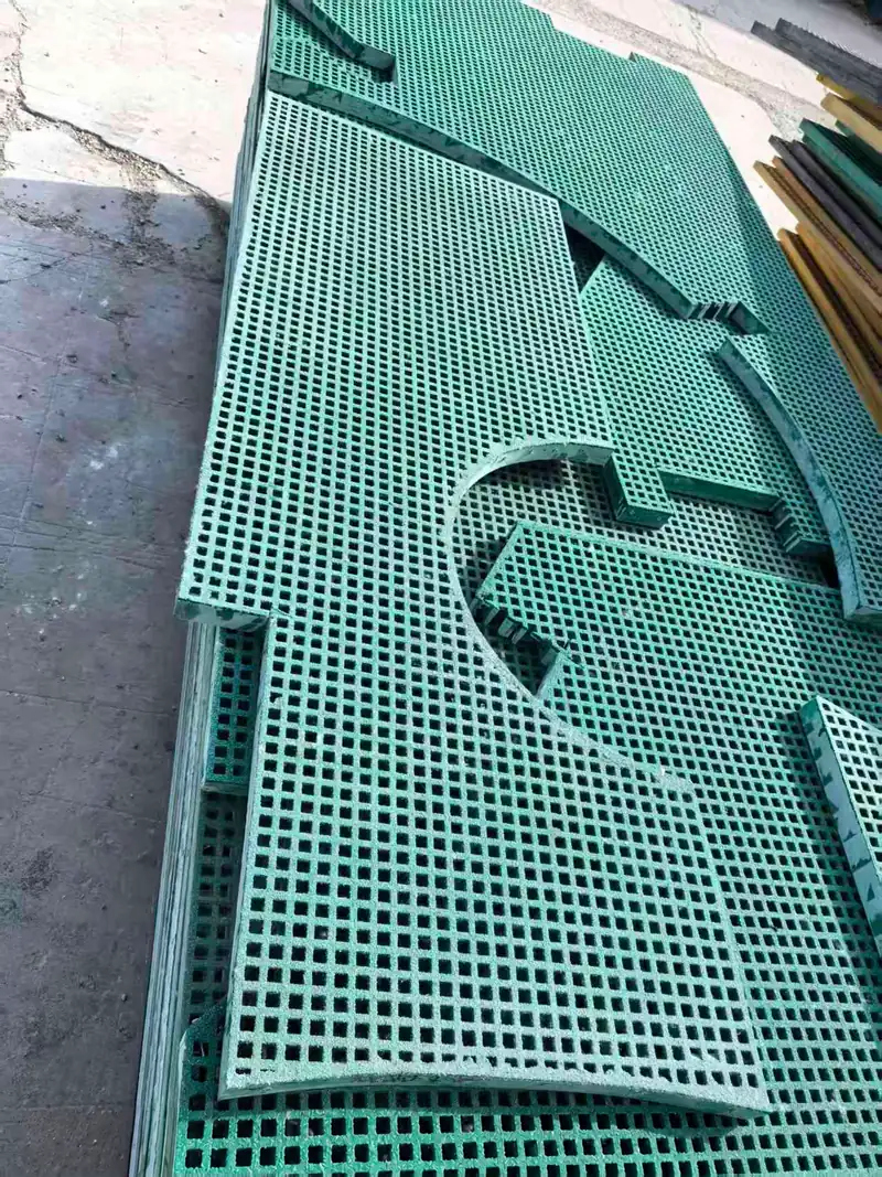
A Practical Installation Sequence at a Glance
The sequence can be reduced to a sentence for a toolbox talk: check the support, dry-lay the panel, cut and seal the pieces, set the bearing, fix the panel, join the edges, support the openings, then inspect and record. The order is deliberately repetitive on site because each step protects the next one. A cut made before the support is measured can be wrong. A fixing made before the bearing is checked can hide a rocking panel. A seal applied before an opening is reviewed can make a structural problem look finished.
The molded grating product guide covers the panel configuration, and the technical resources index links the load, resin, surface, cutting and quality pages that support the installation. If the project uses pultruded panels, start with the pultruded grating guide because the bearing-bar direction changes the layout check.
Acceptance
FRP Grating Installation Checklist
Use this list at delivery and again after fixing. It is written to be checked on site, not filed away with the quotation.
- Drawing revision and piece numbers — Every panel on site can be matched to the approved layout and cut list.
- Support dimensions measured — Beam positions, clear spans and bearing surfaces have been checked against the drawing.
- Panel direction and top face confirmed — Pultruded bearing bars, molded top surface and joint pattern are correct before fixing.
- Cut list and factory-cut pieces checked — Sizes, openings, piece marks and the edges that should already be sealed are confirmed.
- Fixing set complete — Clips, bolts, nuts and washers match the approved type and material, with enough for the positions shown.
- Cutting and drilling controls ready — Suitable tools, blade, dust control, eye and respiratory protection, and a stable work surface are available.
- Opening support agreed — The bars to be cut, the support around the opening and the panel split have been reviewed.
- Edge sealing arranged — A compatible resin and a clean, dry working method are available for every cut or drilled face.
- Final inspection completed — Fixings, joints, steps, rocking, cracks, opening support and edge sealing have all been checked.
- Handover record kept — The revision, fixing type, deviations and any outstanding item are recorded for maintenance and extension work.
Where it is used
Installation Notes by Application
Walkways, covers, solar routes, treatment plants, docks and stairs each put a different demand on the same panel.

Elevated steel walkway
Check beam positions and bearing before dry-laying the run. The walkway in the photo sits on a steel frame with edge trim along the exposed side.

Trench and inspection cover
The frame has to be level and the cover has to sit without rocking. If the cover is lifted for access, agree the lifting points before the fixing layout is finalised.
Solar rooftop walkway
Panels often follow an existing rail or track. Confirm that the rail can take the fixing, that the walkway is clear of the array, and that the panels cannot lift in wind.

Wastewater plant access
Wet, corrosive and wash-down conditions change the fixing material and the inspection routine. The support and the fixing have to suit the actual exposure, not just the panel.

Dock and marine platform
Salt exposure and movement make the clip material and the fixing detail part of the specification. Check the deck edge, lifting points and the condition of the supporting structure.

Stair treads
A tread is a separate product with its own side support, nosing and fixing. Check the stair drawing before treating a cut platform panel as a tread.
Factory experience
A Solar Walkway Order Built Around the Existing Support
A real order record, limited to what the record actually contains.
For a solar maintenance route in Indonesia we supplied 25 mm molded grating with a 38 × 38 mm mesh, cut to 400 × 2000 mm, in unsaturated polyester with a yellow grit surface. The customer already had track supports, so the panels were laid on that support and connected with M clips.
The installation question was therefore not “which clip is standard?” but “which clip fits this panel height and this support, and where does the customer want the fixing points?” The cut size, surface and clips were part of the order rather than left for site work.
This record describes a configuration we supplied. It does not contain the support spacing, clear span, load or deflection limit, so it is a starting point for a similar walkway rather than a design approval for a different roof.

Factory preparation
How We Prepare Grating for Installation
Cutting, sealing, numbering and packing are part of the installation plan when they are agreed before production.
We check the panel sizes against the support layout, bearing direction, openings and fixing arrangement before the order is released to production.
Thickness, mesh, resin, surface and colour are fixed in the quotation and approval drawing. The clip type and fixing positions are listed with the panels.
Pieces are cut and drilled to the approved dimensions, with piece numbers that match the packing list and the site layout.
Where edge sealing is ordered, cut and drilled faces are treated with a compatible resin before packing. The sealing scope is agreed rather than assumed.
The finished pieces are checked for dimensions, appearance and piece marking before they are packed for shipment.
Panels are packed for transport and the agreed clips, bolts and washers travel with the order so the site receives a set that matches the cut list.
Request a review
Send the Layout, Cut List and Fixing Details
A marked-up support drawing and cut list are the fastest way to get a buildable answer.
- Molded and pultruded grating produced in house
- Full panels or factory cut-to-size pieces
- No fixed minimum order quantity
FRP Grating Installation Questions
What is the correct way to install FRP grating?
Is FRP grating the same as fiberglass grating?
What tools do I need to install FRP grating?
Do FRP grating panels need clips?
How many clips should I use per panel?
What torque should the clips be tightened to?
Can FRP grating be cut on site?
Which blade should I use to cut fiberglass grating?
Do cut edges need to be sealed?
How much bearing does an FRP grating panel need?
Do I need to leave a gap between panels?
Can a panel joint carry load?
Can I walk on FRP grating before it is fixed?
How do I install grating around a pipe or column?
Can FRP grating be installed on an existing steel frame?
Does FRP grating installation need welding?
What should I check after installation?
Content last checked: