Solar array maintenance access
FRP Grating Solar Walkways for PV Maintenance
Our usual solar maintenance starting point is 25 mm molded grating, 38 × 38 mm mesh, in isophthalic unsaturated polyester with alumina filler for ordinary environments. Send the rail layout and cut list to confirm the panel, clips and price.

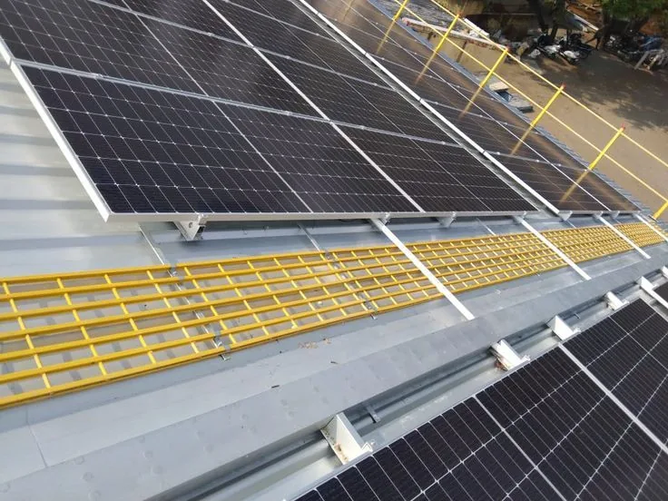
A rooftop maintenance route between PV rows. Photo: Dengtai Industry.
Terms
Solar Walkway Terms Used on This Page
These distinctions matter because a solar walkway is often described with the same words as the module, the support and the fixing.
- FRP grating solar walkway
- An open composite walking surface used beside, between or along rows of photovoltaic modules so people can inspect, clean and service the array. FRP means fiberglass-reinforced plastic; GRP and fiberglass grating are common names for the same glass-reinforced material.
- Solar maintenance walkway
- The access route itself, usually carrying one or two people with hand tools. It is not a vehicle floor, a material storage platform or a substitute for fall protection, guardrails or a project-specific structural design.
- Walkable solar panel
- A different product: a photovoltaic module designed to be walked on. The FRP walkway on this page is laid beside the modules, not on the glass, so the array keeps its own access and maintenance route.
- Rail or track support
- The existing array rail, mounting track or dedicated frame that the walkway panel bears on. The clip connects the panel to that support; the support itself still has to carry the walkway load and any wind uplift.
- Cut-to-size panel
- A grating piece cut to the project list, often a narrow strip between PV rows. Its length and width describe the piece, not the unsupported distance between supports.
- Clear span and bearing
- Clear span is the distance between the edges of two supports. Bearing is the contact between the panel and those supports. A long panel can have a short clear span, and a short panel can sit badly if only one edge bears.
- Molded and pultruded grating
- Molded grating has an integral mesh with bars in two directions. Pultruded grating has parallel I- or T-section bearing bars tied by cross rods, so its main load path is directional. Both can serve a solar walkway, but they are compared on structure, support direction, span and load rather than on thickness alone.
Solar site types
Where an FRP Solar Walkway Is Used
The same panel can be a good fit on one array and the wrong choice on another; the support and exposure decide.
Rooftop array between PV rows
The common cut-to-size case. Narrow yellow strips run between module rows on the array rails, with the walkway kept off the module glass and roof sheet. Wind uplift, rail spacing and fixing points decide the fixing layout.
Send the rail section and spacing, the route width, the piece sizes and the roof exposure.
Ground-mounted solar farm
A maintenance route at grade, often in longer runs and with more joints. A 30 mm or 38 mm molded panel may be considered where the supported run or foot traffic is heavier; the clear span and deflection still have to be checked.
Confirm the support type, ground settlement, route length, joints and whether tools or small equipment are carried.
Coastal or industrial PV site
Salt, cleaning chemicals or process exposure move the resin and clip discussion away from the economical base. Vinyl ester may be the resin direction, and stainless clips may be considered, but the grade and the actual medium still have to be confirmed.
Provide the chemical or salt exposure, cleaning agents, temperature and the project's document requirements.
Retrofit to existing rails
The array is already installed, so the walkway has to fit the rails as built. The rail profile, bolt access, panel height and bar spacing are surveyed before the clip and cut list are fixed.
Send photographs of the rail and a drawing with rail positions, plus the piece list and fixing points.
Panel cleaning and service route
A route used during washing and inspection needs drainage, a surface that suits the cleaning method and a color that keeps the edge visible. The grit texture is a walking surface, not automatically a certified slip rating.
State the cleaning method, frequency, wet or dusty conditions and any slip or fire test the project requires.
Removable walkway sections
Some arrays need panels lifted to reach modules or roof equipment. Smaller pieces, repeatable clip positions and clear piece marks make removal and refitting possible; the support and fixing still have to be designed for it.
Say which pieces are removable, who handles them and how the fixing is released and refitted.
Configuration
Solar Walkway Grating Sizes and Starting Points
Start with the panel, then confirm the support, load and exposure. Mass and base price are not load ratings.
Request a Project Quote| Specification | Value |
|---|---|
| Typical solar maintenance panel | 25 mm molded; 38 × 38 mm mesh; 12.5 kg/m²; USD 10.5/m² EXW Our usual light pedestrian starting point for short supported runs and narrow solar strips. The price is a plain-panel base, not a span or load approval. |
| Stiffer pedestrian option | 30 mm molded; 38 × 38 mm mesh; 16.5 kg/m²; USD 12.0/m² EXW Considered where the supported run or foot traffic calls for more stiffness. Confirm the support layout and deflection limit before using it as an upgrade. |
| Longer or heavier pedestrian option | 38 mm molded; 38 × 38 mm mesh; 19.5 kg/m²; USD 15.1/m² EXW A further molded option, still for pedestrian access. It does not become a vehicle rating and must be checked against the actual span. |
| Full panel sizes | 1000 × 4000; 1220 × 3660 mm Other full-panel formats depend on the mold. Solar pieces are normally cut from these panels, so the cut plan and offcuts matter. |
| Example cut piece | 400 × 2000 mm 0.8 m² per piece. This is a piece area, not the area taken from a full sheet; nesting loss is priced separately. |
| Surface and color | Concave standard; grit, inlaid grit and color to order Grit adds walking texture. It is not a slip rating unless the project's test method and report are supplied. |
| Fixing | M, L and C clips; galvanized or stainless steel The clip is matched to panel height, bar width and support section. The fixing count and positions come from the support drawing. |
| Resin directions | Isophthalic unsaturated polyester with alumina filler; vinyl ester, epoxy and phenolic on request The published base price uses the economical polyester formulation for ordinary environments, not strong corrosive service. |
| Load data | Adopted values for two 6 × 38 mm bar structures The available table covers 38 mm and 19 mm pitch under stated conditions. It is not a rating for every 25 mm or 30 mm panel; the structure and support must match. |
Panel structure
Molded vs Pultruded Grating for Solar Walkways
Both are FRP, but they carry load differently and are not interchangeable on a thickness figure.
| Panel structure | How it carries load | Where it fits a solar walkway | What to confirm |
|---|---|---|---|
| Molded grating, 25 / 30 / 38 mm | An integral mesh with bars in two directions | Short supported runs, narrow strips between PV rows and cut pieces with openings | Thickness, mesh, support spacing, load and deflection as one set |
| Pultruded grating, I or T bars | Parallel bearing bars carry the main load along the bar direction | Longer, straighter runs where a directional panel suits the support layout | Bearing-bar direction, support spacing, panel depth and deflection limit |
| What the comparison does not settle | Either panel can be unsuitable if the support or span is wrong | Either can be cut to a solar route, but the cut plan and edge treatment differ | The project drawing and load case, not the product name |
Project conditions
Solar Walkway Conditions and What Each One Needs
Eight conditions decide the panel and the fixing; each one needs an input from the site.
| Project condition | How we approach it | What we need from you |
|---|---|---|
| Existing rail layout | The panel and clip are aligned to the rail before the cut list is released | Rail section, direction and spacing, with a drawing that marks the support positions |
| Roof or ground support | Roof uplift, roof loading and ground settlement are treated as different support cases | Where the walkway sits, how the supports are fixed and who is responsible for the structure |
| Wind uplift and restraint | Hold-down positions are taken from the layout rather than a fixed clips-per-panel rule | Wind exposure, edge zones, fixing points and any project fixing standard |
| Pedestrian load and tools | The load case starts with who walks the route and what they carry | Number of people, tools or equipment, point loads and any deflection limit |
| Wet, dusty or washed surfaces | Surface texture and drainage are reviewed with the cleaning method | Cleaning agents, frequency, standing water, dust and whether the route is used wet |
| Coastal or chemical exposure | Resin and clip material are reviewed together, against the actual medium | Salt, chemical, concentration, temperature and required service life |
| Narrow strips and openings | The cut plan is checked for edge bars, openings, piece marks and handling | Piece sizes and quantities, hole positions, removable pieces and the drawing revision |
| Access for module maintenance | Removable or liftable pieces are identified before the fixing layout is fixed | Which modules need access, how often, and how the panel is released and refitted |
What a Solar Walkway Is — and What It Is Not
A solar walkway is an access route. On a photovoltaic array it usually runs between module rows, along a roof edge or from an access point to the equipment that has to be serviced. FRP grating gives that route an open, light and corrosion-resistant surface. It does not generate electricity, and it is not a walkable solar panel.
That distinction is worth stating because “solar walkway” is used for several different products. A walkable PV module is a module designed for foot traffic. A solar walkway in this page is a separate FRP route laid beside the modules, carried on the array rails or a dedicated frame. The array keeps its own modules, cables and mounting system.
The walkway is also not automatically a platform. A platform may carry equipment, guardrails or several people; a walkway normally carries one or two people with hand tools. Width, guarding, fall protection and the structural support follow the project’s layout and safety requirements, not the product name.
Why FRP Grating Suits a PV Array
Fiberglass-reinforced plastic is light for its strength, does not rust like steel and does not spark like metal. A 25 mm molded panel has a reference mass of 12.5 kg/m², so a 400 × 2000 mm piece weighs about 10 kg before packing and fixings. That matters on a roof where every kilogram has to be handled and where the array structure may already be fixed.
The open mesh lets water and dust pass through instead of collecting on a solid surface. It can be cut to narrow strips, which is useful when the space between module rows is much smaller than a standard panel. The same panel can be removed in sections where access to a module or roof equipment is needed.
Those advantages do not make FRP a universal answer. The material is non-conductive, but that does not make the whole installation electrically safe; bonding, earthing and clearances remain project requirements. The panel is light, but it still has to be supported and restrained. The mesh drains, but it can still hold dust or cleaning residue if the route is not maintained.
The Rail Layout Comes Before the Panel
On most solar walkways the panel sits on a rail or track that is already part of the array. The first question is therefore not “which thickness?” but “what does the panel land on?” The rail section, its direction, its spacing and the bearing width determine whether a cut piece can sit flat and whether the clip can reach the support.
The panel length is not the clear span. A 2000 mm piece can sit on rails 600 mm apart, or on two supports near its ends with a much longer unsupported middle. The clear span is the distance between the support edges. That, together with the load and the deflection limit, is what the panel has to be checked against.
A rail does not become a bearing support because the grating touches it. The clip connects the panel to the rail, but the rail and its fixings still have to carry the walkway load and any wind uplift. On a roof, the walkway should bear on the array rails or a dedicated support, not on the module glass or frame unless the module manufacturer and the project engineer have approved it.
Choosing 25 mm, 30 mm or 38 mm Molded Grating
The 25 mm, 38 × 38 mm molded panel is our usual light pedestrian starting point for solar maintenance routes. It is the configuration in the Indonesia order record below, cut into 400 × 2000 mm strips. It suits short supported runs where the route is used by maintenance staff with hand tools.
The 30 mm panel is heavier and stiffer, and the 38 mm panel goes further in the same direction. Neither is a guaranteed upgrade for every project: a thicker panel can still fail a deflection limit if the span is too long, and a thinner panel can be adequate if the supports are close enough. The right comparison is the same support layout, load and deflection limit with each candidate configuration.
Pultruded grating is the other direction. Its parallel bearing bars carry the main load along the bar direction, so it can suit longer, straighter runs when the supports run the right way. It is made to project dimensions and quoted per configuration. The molded versus pultruded comparison explains the structural difference; it is not a recommendation to choose one by name.
Load, Span and Deflection on a Solar Walkway
Start with the real use. One person walking carries a different load from two people with tool bags, a replacement module or a cleaning machine. A point load from a tool box or a ladder foot is different again. The project should state the load case it wants the walkway checked for, including any concentrated load and the deflection limit that matters to the users.
Then give the support layout. Mark the rails, their spacing, the bearing width and every unsupported opening. For a continuous run, say whether the panel is treated as a single span or as part of a continuous layout. A panel that is supported at three points does not behave like a simple two-support beam, and the difference belongs to the structural check.
We hold adopted load and deflection values for two 6 × 38 mm bar structures at 38 mm and 19 mm pitch, under stated single-span, short-term, room-temperature conditions. Those values are not a rating for every 25 mm or 30 mm panel. The bar geometry, support condition and material have to match before a figure can be used. The load and span guidance explains what the table does and does not cover.
Surface, Color, Resin and UV Are Separate Choices
The walking surface and the resin system solve different problems. Concave is the standard molded surface. Grit adds a rougher texture for wet, dusty or washed routes. Inlaid grit and milled surfaces are other options. A grit surface is not automatically a certified slip rating; if the project needs a slip test, state the method and the acceptance value.
Yellow is common on solar walkways because it makes the route visible against the roof and the modules. Color is a visibility choice, not a UV rating. Outdoor exposure can change the appearance of a colored panel, and color retention is separate from structural performance. UV exposure is addressed through the resin system and any specified protection.
Resin selection follows the actual environment. The economical base for the published price is isophthalic unsaturated polyester with alumina filler, for ordinary environments. Our experience with this formulation is about three years of service, with cracking from about one year; it is not suitable for strong corrosive service or a long-life target. Vinyl ester, epoxy and phenolic directions are quoted against the duty. The resin selection guide sets out the questions; the surfaces and treatments guide covers the walking surface.
Cutting Narrow Solar Strips Without Hidden Cost
Solar walkways often use narrow pieces because the gap between module rows is fixed by the array layout. A 400 × 2000 mm piece contains 0.8 m², but that is the area of the piece, not the area taken from a full sheet. How many pieces fit on a 1000 × 4000 mm or 1220 × 3660 mm panel, and how much is left as offcut, depends on the cut plan.
That is why cutting is priced on the delivered area with the actual sizes and nesting loss rather than on a universal cut charge per square metre. A quote that compares only the panel rate can miss the difference between a layout that uses the sheet well and one that produces a large amount of offcut.
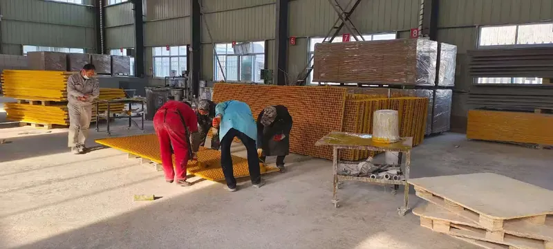
Send the full piece list, quantities and any openings. We prefer factory cutting because the cut edges, drilled faces, piece marks and packing list can be checked together. Cut edges and drilled faces are sealed where the order requires it. An opening still needs support around the remaining cut bars; a hole is not a substitute for a bearing edge. The cutting and sealing guide covers the detail.
Fixing Panels to Solar Rails
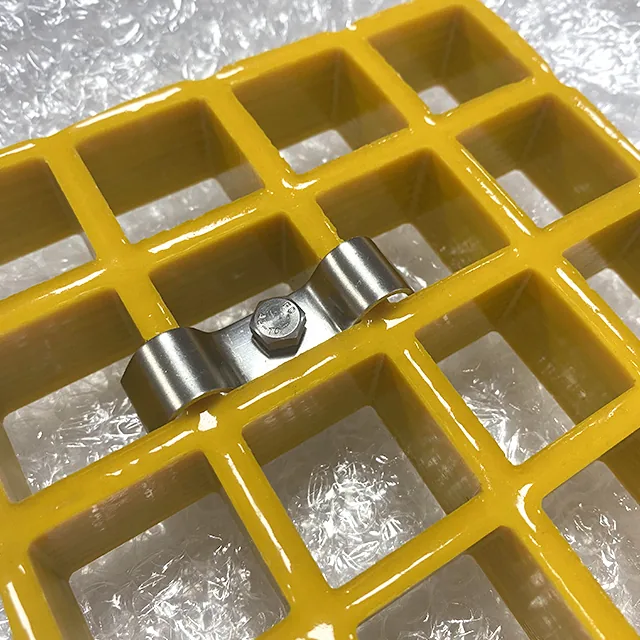
M clips are the usual hold-down for a molded panel. They normally span two adjacent bars and are bolted through the panel to the support below. L clips bear on a single bar at lighter fixing positions. C clips normally join two adjacent panel edges. The letter describes a shape, not a fit: the jaw width, bolt centre and overall height have to match the panel and the rail.
The fixing layout comes from the support drawing. Rail spacing, wind uplift, edge zones, removable pieces and the need to reach the bolt from below all change the number and position of the fixings. We do not publish a universal clips-per-panel figure or a universal bolt torque. Those values are confirmed for the project and recorded on the approval drawing.
Galvanized steel is the economical choice for ordinary access areas. Stainless steel may be considered for coastal, chemical or wash-down exposure, but “stainless” covers a wide range of grades. Tell us the exposure and the support material so the clip and the panel are reviewed together. The clips and fixings guide explains the families and the fit checks.
Price basis
FRP Solar Walkway Price Basis
The panel rate is one line. Resin, cutting plan, surface, clips, packing and delivery determine the usable project price.
The panel rate starts at USD 10.5/m² EXW
The published schedule lists a 25 mm, 38 × 38 mm molded panel at USD 10.5/m² EXW with a reference mass of 12.5 kg/m². A full 1220 × 3660 mm sheet is 4.4652 m², so its plain-panel amount is about USD 46.9 before cutting, surface treatment, clips, packing and freight. A 1000 × 4000 mm sheet is 4.0 m², or about USD 42.0 on the same basis.
The base resin is economical, not a long-life promise
The USD 10.5 row uses our named isophthalic unsaturated polyester resin with alumina filler, for ordinary environments. Our experience with this formulation is about three years of service, with cracking from about one year. It is not suitable for strong corrosive service or a long-life target; vinyl ester, epoxy and phenolic directions are quoted against the actual duty.
Cutting, surface, clips and freight are separate scope
Factory cutting is priced on delivered area with the actual sizes and nesting loss; there is no universal USD/m² cutting surcharge. Grit, color, edge sealing, clips, packing and freight are separate lines. When comparing suppliers, ask whether the quote uses piece area or sheet area and whether nesting loss is included.
Price basis: 17 October 2026, with a fixed planning conversion of USD 1 = CNY 6.5. An issued quotation confirms the current price, currency, scope and validity. The USD 10.5 row is a plain-panel base only; it is neither a project load rating nor a corrosion approval.
Quote anatomy
What Changes a Solar Walkway Quote
Compare the same panel configuration, cut plan, clip quantity and delivery term before comparing the rate.
| Quote item | Published or usual basis | What changes it |
|---|---|---|
| 25 mm molded panel | USD 10.5/m² EXW; 12.5 kg/m²; 38 × 38 mm mesh | Full-panel format, mold, mesh and bar geometry |
| 30 mm molded panel | USD 12.0/m² EXW; 16.5 kg/m²; 38 × 38 mm mesh | Supported run, foot traffic, deflection limit and selected mold |
| 38 mm molded panel | USD 15.1/m² EXW; 19.5 kg/m²; 38 × 38 mm mesh | Longer or heavier pedestrian use, support spacing and load case |
| Resin direction | Isophthalic polyester with alumina filler for ordinary environments | Chemical or salt exposure, temperature, service life and supporting data |
| Surface and color | Concave is standard; grit, inlaid grit and color are quoted | Wet or dusty use, cleaning method, visibility and any test requirement |
| Factory cutting | Priced on delivered area with actual sizes and nesting loss | Number of sizes, narrow strips, offcuts, openings, sealing and piece numbering |
| Clips and hardware | M, L and C clips in galvanized or stainless steel, listed separately | Panel height, jaw fit, support section, fixing count and exposure |
| Packing and delivery | EPE foam, stretch film, wooden pallets and iron supports; export quotes usually FOB | Piece size, quantity, loading port, destination and agreed delivery scope |
| Worked example | 60 pieces at 400 × 2000 mm = 48 m² of piece area; USD 504 at the 25 mm base rate before nesting loss | Cut plan, actual sheet yield, edge sealing, surface, clips, packing and freight |
| Sample and production | Standard 3 × 3 cell sample free with customer-paid freight; no fixed minimum order | Custom sample, panel configuration, order quantity; production normally 15–30 calendar days from deposit |
Installation sequence
How a Solar Walkway Is Installed
Survey the support, settle the piece list, then cut, fix and inspect in that order.
Record the rail section, direction and spacing, the support positions, the route width and every place where the walkway meets a module frame, roof sheet or existing structure. Mark the clear span rather than only the panel length.
Draw the access points, turns, crossings, openings and removable pieces. Give each piece a mark that matches the packing list and the installation drawing.
Select thickness, mesh, resin, surface, color and clip type against the load, exposure and support. Resolve the fixing points and wind restraint before production.
Cut pieces to the approved list, seal cut edges and drilled faces where required, and mark each piece to the layout. Pack with edge protection and a packing list that matches the drawing revision.
Protect the roof surface, keep the walkway off module glass, and dry-lay pieces where the site allows it. Check full bearing, level joints and tool access before fitting the agreed clips. Do not force a clip to pull a panel onto a support it does not reach, and do not use the module frame or roof sheet as a shim.
Check rocking, joint steps, missing hardware, cracked bars, cut-edge condition and access around removable pieces. Record the drawing revision and any site deviation before handover.
Responsibility boundary
Where a Solar Walkway Supply Stops
Clear limits protect the project and keep a panel quotation from being mistaken for structural or fall-protection approval.
- A panel quotation is not a structural design — We supply the panel, cut pieces and agreed fixings. The support structure, roof loading, wind uplift, guarding, fall protection and any temporary works approval remain project responsibilities unless they are separately specified in writing.
- The PV module is not a walkway support — The walkway should bear on the array rails or a dedicated support, not on the module glass or frame unless the module manufacturer and the project engineer have approved that arrangement. A neat fit against a module is not evidence that it can carry a person.
- Panel thickness is not a load rating — 25 mm, 30 mm and 38 mm are configurations, not three guaranteed load classes. Span, support condition, bar geometry, load and deflection limit decide whether a panel is suitable.
- A clip does not create a support — M, L and C clips restrain a panel or join edges. They do not increase the allowable span and do not turn a rail into a bearing support if the rail is not designed to carry the walkway.
- Grit, UV and fire are separate requirements — Grit changes the walking texture. UV exposure is addressed through the resin system and any specified protection. Fire performance needs a named test standard and a report for the exact configuration. None of these follows from the color or the word “anti-slip”.
Order record
What One Solar Order Record Shows
A real configuration is useful, provided its limits are stated with it.
One solar order record we can describe is a shipment to Indonesia: 25 mm molded grating, 38 × 38 mm mesh, cut to 400 × 2000 mm, yellow with a grit surface, in unsaturated polyester, laid on the customer's existing track supports and connected with M clips.
The record is useful because it shows a real cut piece and fixing method for a solar route. It is deliberately limited: it does not include the rail spacing, clear span, load, deflection limit, resin grade, site photographs or a structural approval.
We use it as a starting point for discussion, not as a template to copy. A new project still has to send the rail drawing, piece list, load and exposure before the configuration is confirmed.
The order record proves what we supplied; it does not prove what the walkway can carry.
The photograph below is a separate Dengtai solar walkway reference, not a photograph of this order. Photo: Dengtai Industry.

Factory evidence
What We Can Confirm Before Shipment
Manufacturing, cutting and packing are factory scope; the material report is evidence at the level it actually covers.

Material test report, with its limit
Report HZTC/BG-24051102, issued on 17 May 2024 by Hebei Haozheng Testing Services Co., Ltd., records appearance, Barcol hardness 45, water absorption 0.335%, oxygen index 28.5%, tensile strength 74.2 MPa, and a load test at a design load of 4 kN/m² over a 600 mm span. The report does not name the model, thickness, mesh or resin, so it is material-level evidence rather than a rating for a specific solar walkway panel.
Factory cutting and piece marking
A checked cut list is the normal route for solar strips. Pieces are cut, cut edges and drilled faces are sealed where required, and marks are carried through to the packing list. Openings still need support around the remaining cut bars.
Read the cutting and sealing guidePacking and loading record
Export orders are usually packed with EPE foam, stretch film and wooden pallets or iron supports. We can provide packing photographs and the packing list; a project-specific inspection or third-party certificate is quoted separately when required.
Review quality and documentationProject inputs
What to Send for a Solar Walkway Quote
Nine items give enough information to review the layout, select a panel direction and price the actual supply scope.
- Array and site — Rooftop or ground-mounted, coastal or inland, and whether the array is already installed.
- Rail drawing — Rail section, direction and spacing, support positions, bearing width and clear span.
- Route layout — Walking width, access points, turns, crossings with cables or equipment, and how the route meets the roof edge.
- Piece list — Length × width and quantity for each piece, including narrow strips, openings and removable pieces.
- Use and load — Who uses the route, what they carry, how often, and any deflection limit or point-load requirement.
- Fixing and wind — Clip type, material, fixing points and the wind-uplift or restraint requirement from the project.
- Exposure — Sun, rain, dust, salt, chemicals, cleaning agents, temperature and expected appearance or service life.
- Surface and documents — Concave or grit, color, edge sealing, and any slip, fire or other test standard the project requires.
- Delivery — Destination, trade term, packing preference and required production or delivery date.
Request a quote
Send Your Rail Layout and Cut List
The support drawing and the piece list are the two documents that matter most.
- Molded and pultruded grating produced in house
- Full panels or factory cut-to-size pieces
- No fixed minimum order quantity
FRP Solar Walkway Questions
What is an FRP grating solar walkway?
Is a solar walkway the same as a walkable solar panel?
What thickness should a solar walkway use?
How much does an FRP solar walkway cost?
Is the price per square metre or per piece?
Can you cut panels to 400 × 2000 mm or other solar sizes?
How is the grating fixed to solar rails?
Can the walkway sit on the PV module frames?
Is FRP suitable for coastal or chemical solar sites?
Does a grit surface make the walkway slip-resistant?
Will the color fade in UV?
What is the minimum order and lead time?
Can you supply pultruded grating for longer spans?
What documents can you provide?
Content last checked: