Pultruded grating opening guide
Pultruded Grating Bar Spacing, Openings and Open Area
Bearing-bar pitch, clear opening, top-flange width and cross-rod spacing are separate fields. Open-area percentage is useful for comparison, but it does not describe the local gap seen by a foot, wheel, tool or drain.
Prepared by
Dengtai Industry
Published
·
Reviewed

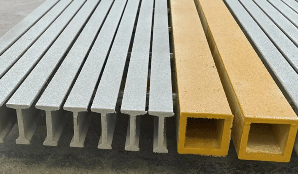
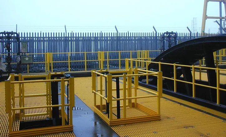
The apparent top pattern contains multiple dimensions. Record the exact measurement instead of choosing by open-area percentage. Photo: Dengtai Industry.
Measurement terms
Pitch, Clear Opening, Cross-Rod Spacing and Open Area
Four measurements answer four different questions about the finished walking surface.
- Bearing-bar pitch
- The centre-to-centre repeat distance between adjacent bearing bars, often called load-bar centres. It is not the clear gap between their top flanges.
- Top-flange width
- The width of a bearing bar across its walking surface. Clear opening can change when this width changes even if the bearing-bar pitch remains the same.
- Clear opening
- The actual unobstructed gap seen from one side of the finished grating to the other at the stated measuring plane. It can vary between the top flanges, webs and lower flanges, and can change with surface, edge bars, cross rods and adjacent details.
- Cross-rod spacing
- The repeat distance between transverse rods measured along the bearing bars. It is independent of bearing-bar pitch and may be specified separately.
- Open area
- The proportion of the nominal panel surface that is open. It is useful for drainage, ventilation and general comparison, but does not describe the shape or minimum clear gap.
- Local opening
- The finished opening at a specific location, after edge bars, clips, a joint or a cutout have been added. This is the value relevant to a wheel path or installation detail.
- Accessibility opening
- A clear opening evaluated for the applicable user and project criterion. A nominal open-area percentage is not an accessibility measurement.
Opening comparison
What Open Area and Clear Opening Each Describe
One describes a panel proportion; the other describes the local passage seen by a user or object.
Swipe horizontally to view all columns.
| Measurement | What it describes | What it does not establish |
|---|---|---|
| Bar pitch | Repeating centre-to-centre distance of the bearing bars. | The clear gap after bar width and surface are included. |
| Clear opening | The actual local gap at a stated plane and finished location. | Open-area percentage or suitability for every wheel and user. |
| Cross-rod spacing | Distance between transverse connecting rods along the bars. | Main bearing-bar pitch or overall open area. |
| Open area | Share of the nominal panel surface that is open. | The smallest gap or the opening at an edge or joint. |
| Wheel contact | The loaded wheel width and the route direction. | A numerical clearance from open area alone. |
| Drainage | Available flow path, direction and blockage potential. | A generic “high open area equals better drainage” conclusion. |
Traffic review
When Bar Spacing Needs a More Detailed Check
Increase the review when small wheels, accessibility, drainage, debris or turned panels are involved.
Specify this if…
- Use this review when the panel must pass small wheels, feet, tools, debris or drainage.
- Use it when two products have similar open-area percentages but different bar geometry.
- Use it when panel direction, joints or cut edges affect the opening a user sees.
- Use it when public access or a project accessibility criterion applies.
Look elsewhere if…
- Do not select a panel from its open-area percentage alone.
- Do not treat bearing-bar pitch as clear opening.
- Do not use a measured sample unless its finished direction and surface match the order.
- Do not compare a narrow wheel against an average opening.
- Do not assume an ADA or local accessibility requirement from a nominal mesh description.
Measurement sheet
Fields to Record on the Finished Pultruded Grating
Identify the product pattern, the measuring plane and the completed installation detail.
Swipe horizontally to view all columns.
| Measurement field | How to record it | Why it matters |
|---|---|---|
| Bearing-bar pitch | Centre-to-centre distance along a straight run of bars. | Identifies the product row and repeat pattern. |
| Top-flange width | Measure the bar width at the walking face. | Combines with pitch to describe the nominal open gap. |
| Clear opening | Measure edge-to-edge at the stated plane and location. | Relates to feet, small wheels, tools and debris. |
| Cross-rod spacing | Measure centre to centre along the bearing bars. | Describes transverse repeat, which may constrain small objects. |
| Panel direction | Record the bearing-bar direction and the direction of travel. | A wheel or foot crosses the grid differently at different angles. |
| Edge and joint detail | Measure the actual opening after edge bars, connectors or supports. | The catalogue pattern is not the complete installed opening. |
| Surface | Record grit or other top finish and measured projection or thickness where required. | Surface can change contact and the opening seen at the top. |
| Open area | Take the value from the exact product row and note its basis. | Useful for panel-level drainage comparison, not local clearance. |
Pultruded grating bar pitch, clear opening and open area are not the same measurement. Pitch is centre-to-centre spacing, clear opening is the actual local gap, and open area is the percentage of the panel surface that is open.
Cross-rod spacing adds a fourth dimension. It is separate from bearing-bar pitch and can influence what passes through the finished grid. Select the product row and evaluate the traffic requirement together.

Start With the Exact Product Row
Record:
- I, T or WT profile;
- nominal depth;
- bearing-bar pitch;
- top-flange width;
- cross-rod spacing;
- open-area basis;
- surface;
- panel direction.
The pultruded product page lists current series dimensions. The section guide explains how to compare the complete profile.
Confirm the bearing-bar direction in the pultruded direction guide before comparing any local gap. The size and weight guide also separates nominal size, actual size, pitch and open area.
A series code may contain depth, pitch, open area or a supplier-specific identifier. The numbers do not have to mean the same thing across manufacturers. Translate the code into measured product fields and use the supplier’s own drawing before comparing two offers.
Pitch Is Centre-to-Centre
Bar pitch is commonly measured from the centre of one bearing bar to the centre of the next. It is the repeating module of the panel.
Pitch does not equal clear opening because bar width occupies part of the repeat. A wider top flange can reduce the visible gap at the same pitch.
For a simplified straight-bar check:
nominal top gap ≈ pitch − top-flange width
This is a dimensional cross-check, not the final open-area calculation. Cross rods, surface geometry and the exact profile can change the result.
Worked Example Using Our 38 mm Rows
Our product schedule includes 38 mm rows with different top-width and open-area values.
For the T38-33 row, the schedule lists:
- a 38 mm bearing-bar pitch;
- a 25 mm top width;
- 33% open area.
Using the simplified top-view check, the nominal gap between those flange edges is about:
38 − 25 = 13 mm
For the I38-60 row, the schedule lists:
- a 38 mm bearing-bar pitch;
- a 15 mm top width;
- 60% open area.
The same check gives:
38 − 15 = 23 mm
For the WT38-12 row, the schedule lists:
- a 43.5 mm bearing-bar pitch;
- a 38 mm top width;
- 12% open area.
The top-view check gives:
43.5 − 38 = 5.5 mm
These rows all have a nominal 38 mm depth, but their top geometry, mass and open area differ. The calculation is useful for comparing the top flange, but it does not replace a measured clear opening on the finished product.
It also does not approve a 5.5 mm, 13 mm or 23 mm gap for a particular foot, wheel, accessibility requirement or drainage condition. Cross rods, surface, direction, local edges and the applicable acceptance method still need review.
Pitch Also Changes the Panel Structure
Pitch affects more than the opening. For a given panel width and bearing-bar profile, changing the pitch changes how many bars are assembled into that width. A closer pitch generally adds bearing bars, increasing material and mass while reducing the open space. A wider pitch uses fewer bars and produces a lighter, more open panel.
That does not make one direction “stronger” in every load case. More bars across the width can improve how a distributed action or a small footprint is shared, but the result still depends on the exact profile, depth, resin, span, end bearing, local load position and permitted deflection. A panel with a tighter pitch can also fail much earlier than a different, deeper product row.
Use the load table that names the same section and pitch and states its support and deflection conditions. Do not estimate capacity by scaling the number of bars alone, and do not assume that extra material automatically solves a local wheel or cutout condition.
The commercial effect is similar. A more open panel may use less material, but a narrower support spacing, deeper section, extra edge framing or additional fixing can remove that saving. Compare the installed layout and evidence rather than a price per square metre for an unnamed mesh.
Clear Opening Is the Local Gap
Clear opening is measured edge to edge at a stated plane. Record:
- the measuring plane;
- the direction of measurement;
- whether the location is between bearing bars or across a more complex grid;
- edge bars, joints and fixing details;
- whether the item is a sample or full finished panel.
A single nominal clear-opening value may not describe every point on the panel. The local opening is the useful value for a wheel, foot or tool.
Top and Underside Gaps Can Differ
The top flange and the narrower web or lower-flange zone do not necessarily produce the same clear space. This is especially important for I and wide-T profiles. A dimension between top flanges does not establish the distance between webs or lower flanges. Cable clearance, tools, wheel penetration, fixings and some inspection methods may depend on another plane.
Our product table identifies the top width b, but it does not contain every bottom-flange or web dimension. Obtain the section and assembly drawings when the underside matters. Record whether the measurement was taken at the walking surface, between webs or between lower flanges.
Cross-Rod Spacing Is Separate
Cross rods connect and stabilise the bearing bars. Their spacing is measured along the bars, generally centre to centre.
It is not:
- the bearing-bar pitch;
- the clear opening between the top flanges;
- the principal span direction.
The finished top grid may therefore have one repeat pattern across the load bars and another along them. Both can affect dropped objects and small wheels. Keep the bar direction and the finished-grid direction visible in the same review.
Open Area Is a Panel Proportion
Open area describes the share of the nominal panel that is open. It is useful for:
- drainage comparison;
- ventilation;
- general self-cleaning potential;
- comparing patterns at the panel level.
It is not:
- the minimum clear opening;
- the wheel path through a finished joint;
- proof that an accessibility requirement is met;
- a replacement for a local blockage and flow review.
Two patterns with the same open-area percentage may form different opening shapes and edge conditions.
The broader FRP mesh and opening guide compares other mesh formats and the access tasks they are intended to serve.
Compare Same-Depth Profiles as a Useful Cross-Check
Our current schedule includes 38 mm rows with different top-flange widths and open-area values. This demonstrates why depth alone is insufficient.
Use the product row table to compare pitch, b and open area. Then:
- confirm the profile drawing;
- measure the clear opening;
- check the surface;
- evaluate the required traffic.
Do not calculate one product’s opening and apply it to another profile with the same nominal depth.
Check the Direction of Travel
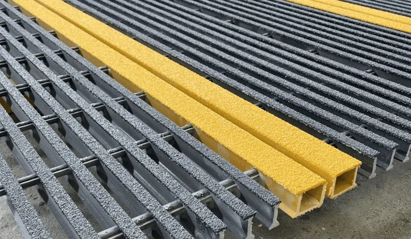
The opening seen by a wheel, foot or tool can vary with its route relative to the bars and cross rods.
Record:
- main walking or wheel direction;
- turning areas;
- wheel width and contact;
- foot size or footwear requirement;
- tools or dropped objects;
- objects that must pass below.
For a trolley route, a route drawing is more useful than a single “wheel diameter” note. The platform grating guide is the next review when local loads interact with the opening.
Finished Edges and Joints Change the Local Opening
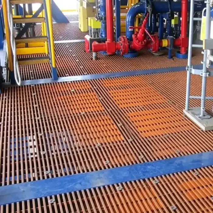
The catalogue pattern is not the complete installation. Check:
- edge bars and end closures;
- connectors and clips;
- joints between panels;
- cut pieces and partial openings;
- solid or covered strips;
- frames and trims.
A wide pattern can become locally restrictive near an edge, while an added frame may create a new opening elsewhere.
Review clip fit and edge details in the fixings guide before treating the nominal top opening as the finished installation condition.
Drainage and Blockage
Open area supports a drainage comparison, but the flow path also depends on:
- bar orientation;
- slope;
- cross rods;
- debris shape;
- cleaning;
- accumulated material;
- covered areas and edge closures.
For a drainage application, show the flow direction and debris expected. A large open area may still blind if the geometry traps fibers or solids.
Record the Opening on the Finished Product
A useful opening record contains:
| Field | What to record |
|---|---|
| Product row | I, T or WT profile, depth and pitch |
| Direction | Bearing-bar direction and direction of travel or flow |
| Top geometry | Bar/flange width and surface finish |
| Bar pitch | Measured centre-to-centre pitch |
| Clear opening | Measured top or underside edge-to-edge gap and stated plane |
| Cross-rod spacing | Measured centre-to-centre along the bars |
| Open area | Product value and its stated basis |
| Local details | Edge bars, clips, joints, cutouts or framing |
| Requirement | Foot, wheel, tool, debris, drainage or accessibility criterion |
| Result | Pass, hold or project-specific disposition |
This makes the difference between a product-description check and a finished-opening approval visible to everyone reviewing the delivery.
Accessibility and Public Access
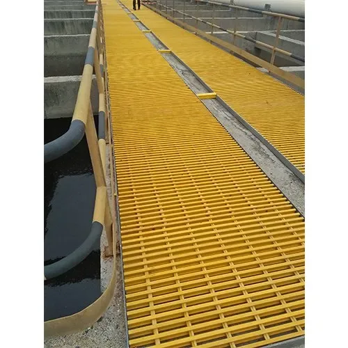
An accessibility requirement may specify a measuring method, probe, direction, opening shape or maximum gap. Do not infer compliance from a nominal “small mesh,” the bearing-bar pitch or an open-area percentage.
The U.S. Access Board’s ADA floor-and-ground-surface guidance adds two direction-specific checks for applicable accessible routes. Openings must limit passage of a ½-inch sphere, and elongated openings must place the long dimension perpendicular to the dominant direction of travel. Where there is no dominant direction, the guidance limits the openings in both dimensions; it also addresses locations where an accessible route can bypass the openings.
That makes the installed bearing-bar direction part of the accessibility review, not only the structural review. Use the dominant route direction, the actual finished opening shape and the governing standard together. A product description, a top-view drawing or an open-area percentage cannot establish compliance by itself.
State:
- the applicable standard or project criterion;
- the dominant direction of travel;
- what is measured;
- the test or acceptance method;
- whether the measured plane is the finished top or underside;
- whether the finished surface, edges and joints are included.
How to Measure the Finished Grating
Use a finished sample or delivered panel in its installed direction:
- identify the bearing bars and cross rods;
- mark a straight run away from an edge or local repair;
- measure several bearing-bar pitches centre to centre;
- measure top-flange width on the same bars;
- measure the clear opening edge to edge at each required plane, including the underside where relevant;
- measure cross-rod spacing along the bars;
- repeat at the agreed sample locations;
- record the dominant travel direction and route angle;
- record instrument, panel mark and drawing revision.
For a wheel or foot check, also record the route angle relative to the bars. A caster entering the grid diagonally can see a different local gap from one travelling parallel to either axis.
Do not measure only the largest opening. If the acceptance criterion concerns the smallest passage, the largest area of the panel is not necessarily representative.
Why Open Area Cannot Be Back-Calculated From One Gap
Open area depends on the complete pattern, including bearing bars, cross rods and surface geometry. A single clear-gap measurement does not contain enough information to reproduce the panel’s open-area percentage.
Likewise, an open-area percentage cannot be converted into one local gap without the complete drawing. Use the product value for panel comparison and the measured local geometry for traffic and edge checks.
Common Opening-Selection Mistakes
- Treating load-bar centres as the clear gap.
- Quoting open area but not the clear opening.
- Measuring across the wrong direction.
- Measuring only the top plane when an underside or web clearance controls.
- Comparing the sample in one orientation to the installed route in another.
- Ignoring cross-rod spacing.
- Ignoring edge bars, clips and joints.
- Inferring accessibility from a generic mesh size.
- Orienting elongated openings along, rather than across, the dominant route of travel.
- Treating open-area percentage as a drainage guarantee.
The Manufacturer Rule for Bar Spacing
Identify the full profile and record pitch, top-flange width, clear opening, cross-rod spacing and open area separately. Then test those dimensions against the actual traffic, object and finished installation detail.
Use the percentage to compare panels. Use the local opening to understand what passes.
Opening method
From the Actual User or Object to the Measured Opening
Define what must pass before comparing a product pattern or an open-area percentage.
Record feet, wheel width, tool size, debris, flow and the main travel direction.
Link profile, depth, pitch and cross-rod spacing to the offered grating.
Record the actual clear opening at the relevant plane and location.
Review the opening created by the completed installation detail.
Use the percentage for drainage and ventilation, not as a proxy for local clearance.
State the project criterion and whether a sample, drawing or test is required.
Evidence boundary
What a Product Sample and Drawing Can Support
Measurements can be documented, but acceptance depends on the project criterion and finished configuration.

Exact product row
Profile, depth, pitch, top width and cross-rod spacing are confirmed rather than inferred from a general mesh label.
Finished geometry
The clear opening and measuring plane are recorded on the sample or delivered product.
Direction considered
Wheel, foot, tool and drainage checks use the direction of travel or flow relative to the bars.
Local details included
Edge bars, clips, joints, frames and cutouts are part of the finished opening.
Open area kept separate
The product percentage is reported as a panel metric, not as proof of a local clearance.
Acceptance method
The project or accessibility criterion and measurement method are stated before the result is approved.
RFQ checklist
What to Send for a Pultruded Opening Review
Include the product row, traffic, small-object, drainage and accessibility conditions.
- Product profile — I, T or WT series, depth, bar pitch, top-flange geometry and the measured underside plane where relevant.
- Cross-rod spacing — The transverse repeat distance and any required alignment between panels.
- Traffic and users — Footwear, trolley or wheel dimensions, dominant travel direction, turning, maintenance equipment and frequency.
- Objects and drainage — Small objects that should not pass, flow direction, debris load and cleaning method.
- Openings and edges — Cutouts, joints, edge bars and frames that modify the local open space.
- Accessibility criterion — The governing standard or project requirement, without assuming a nominal mesh satisfies it.
- Measuring method — Measurement plane, instrument and whether the sample or finished panel is inspected.
- Required evidence — Product drawing, measured sample or project-specific data needed for acceptance.
Request a review
Send Your Pultruded Grating Traffic Requirements
Describe what must pass, what must not pass and how the finished route will be used.
- Pitch and clear opening separated
- Finished direction and edges considered
- Accessibility claim kept testable
Pultruded Grating Spacing and Opening Questions
Is pultruded grating bar spacing the same as clear opening?
What is the difference between open area and clear opening?
Does higher open area always improve drainage?
Where should I measure clear opening?
Is cross-rod spacing part of bearing-bar pitch?
Can a small wheel cross grating with high open area?
Does a nominal 19 mm opening meet an accessibility standard?
Can I measure a sample instead of the finished panel?
Does closer bearing-bar spacing increase load capacity?
Can the top and bottom clear openings be different?
Does bearing-bar direction matter for ADA-accessible routes?
This content was prepared and reviewed by Dengtai Industry’s technical and production team using the project conditions, available product data and applicable documents. Limits that require design, testing or approval are identified in the content. Content last checked: