FRP grating movement review
FRP Grating Thermal Expansion Gaps: What to Check
There is no universal gap to copy from another project. Start with the panel run between fixed points, the approved material coefficient, the installation and service temperatures, and the actual clip or edge restraint. Then calculate movement and record the joint detail before cutting.
Prepared by
Dengtai Industry
Published
·
Reviewed

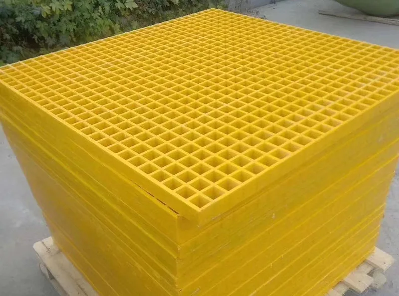
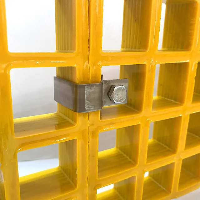
Long exposed runs show why the joint gap, fixed points and restraint must be coordinated. Photo: Dengtai Industry.
The Short Answer: Calculate the Run, Then Design the Joint
An FRP grating panel changes length as its temperature changes. The first useful calculation is:
ΔL = L × α × ΔT
where L is the run between fixed points, α is the approved material coefficient for the ordered product and ΔT is the temperature difference from the installation condition to the relevant hot or cold extreme. This gives free thermal movement for that run.
It does not, by itself, give the gap to cut. The approved joint must also account for the fixing arrangement, edge clearance, manufacturing and installation tolerance, the direction in which movement is allowed and the condition of the support structure. A panel trapped by clips at both ends can develop stress even when the drawing shows a gap between two other panels.
A worked arithmetic example, not a product value
For illustration only, assume a 3000 mm run, an approved coefficient of 0.000012 /°C and a 50°C difference between installation and the governing extreme:
3000 mm × 0.000012 /°C × 50°C = 1.8 mm
The 1.8 mm is the calculated free movement, not the final gap and not a Dengtai product coefficient. Replace all three inputs with the actual panel data and project temperatures. Calculate movement toward both the hot and cold extremes and use the larger governing case for the joint review.

Why Published Gaps Cannot Be Copied
Search results and installation pages contain several common figures: 3–5 mm between panels, 6 mm per metre, or 1/4 in. These numbers can be reasonable within a named product system and a particular set of assumptions, but they are not interchangeable.
The Unicomposite installation guide describes a gap per metre. The FRP Grating Master installation page describes a 3–5 mm panel gap. The Bedford fabrication and installation manual shows the kind of product-specific fabrication and fixing detail that must accompany such a number.
Different values on competing pages are not proof that one page is careless. They show the underlying variables: panel construction, product coefficient, installation temperature, fixed-point spacing, clip detail and the intended appearance of the joint. A universal gap detached from those inputs is not a controlled specification.
Start With the Installed Run
Measure the length that can actually move. If a panel is fixed at one end and free at the other, its effective run may be one panel. If several panels are connected or clamped between fixed frames, the accumulated length may be much greater.
Mark the fixed points on the layout. Show:
- which panel or support location prevents movement;
- which direction remains free;
- how each clip, hole or slot allows that movement;
- where edge clearance occurs;
- whether guardrails, curbs, pipes or equipment create another fixed point; and
- whether the support beams themselves expand in a different direction.
The distance between fixed points should be used in the calculation. Counting panel joints without checking their restraint can divide a continuous run into imaginary short panels that do not behave independently.
Capture the Temperature That Controls the Detail
Use three temperatures where possible:
- the temperature of the panel and support when it is fitted;
- the highest credible surface or process temperature in service; and
- the lowest installation or service temperature.
Air temperature can be easier to record, but in a solar-exposed roof or an outdoor process platform the surface may become much hotter. Hot washdown, steam, radiant heat and cold ambient conditions can create different extremes. Record the source and time of each value.
The installation temperature is easy to omit and important. The panel is fitted into a support frame at one actual condition. Movement from that point to the hot or cold extreme is the relevant change for the installed joint.
Measurement and fit-up should also begin from a known condition. Peer installation guidance sometimes recommends letting panels reach site temperature before cutting, but a blanket time does not fit every product or climate. Use the approved installation procedure, record the panel and support condition, and do not measure a distorted panel in direct sun and treat that one reading as the fabrication datum. The factory can mark the approved cut size; the site still has to prepare and check the support before installation.
Do Not Put a Sliding Label on a Standard Fixing
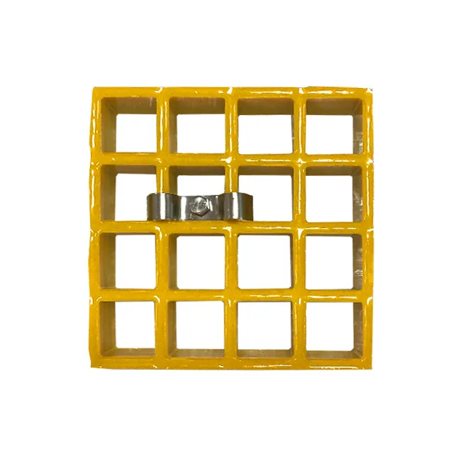
A joint detail may use a fixed and a sliding condition, but the geometry must support that description. A clipped panel can still be trapped if:
- the clip jaw grips both faces tightly;
- the bolt hole has no movement allowance;
- the panel bears against a curb or frame;
- the adjacent panel is similarly restrained; or
- the support surface is uneven enough to lock the panel.
If a slot, slotted clip or clearance is required, its direction, length, edge distance, washer and fastener must be shown. The factory can produce an agreed hole or slot, but it should not infer the structural movement direction from the panel outline.
Separate the Joint Gap From Edge Clearance
A gap between two panels and a free distance to a curb, wall or opening are not the same detail. An edge clearance may be needed for movement, fitting or both, while a panel-to-panel joint also controls alignment, differential deflection and edge appearance.
Show both on the drawing. A joint can have a suitable width while its ends are trapped against a wall. An edge can have a generous gap while the clips prevent sliding. The installation review must follow the whole movement route rather than a single dimension.
Creep Is a Different Service Question
Thermal expansion is reversible movement driven by temperature. Creep is additional deflection under a sustained load, with time, temperature, moisture and product structure influencing the result. Both can appear on a long hot platform, but one cannot be used as evidence for the other.
If an equipment load remains on the panel at high temperature, ask for the relevant sustained-load evidence and deflection limit separately. The FRP grating temperature and creep guide explains the timeline and evidence boundary in more detail.
Our Factory View
We can control the final cut length, squareness, piece mark, approved slot or hole geometry, edge treatment and packing sequence. We can also keep panel IDs and movement directions consistent through the cut list.
We do not infer the structural fixed points, approve a clip as sliding, choose a project coefficient or publish a universal millimetre gap. When those details are open, the item remains a technical hold rather than becoming an assumed factory standard.
Final Movement Rule
Calculate the free movement, map the points that prevent it, design the fixing that allows it and record the result in the joint schedule. If the run, coefficient, temperature range or restraint is missing, the responsible answer is another required input, not a copied gap.
Technical References and Limits
The Fibergrate engineering guide and the Bedford fabrication and installation manual show how manufacturer-specific support and fixing details are documented. The peer installation pages are useful for identifying the questions to ask, but their coefficients, gaps and torque values belong to their named systems.
The approved product coefficient, structural restraint, temperature record and joint calculation for the actual Dengtai order remain the controlling basis.
Movement vocabulary
Ten Terms That Turn Thermal Expansion Into a Joint Record
Length, temperature, coefficient and restraint must describe the same panel run.
- Thermal movement
- The reversible change in panel length with temperature. It is screened with the actual material coefficient, the run between fixed points and the temperature difference.
- Coefficient of thermal expansion
- The material-dependent change in unit length per temperature change. Use the value supplied for the ordered construction and direction, not a generic FRP label.
- Installation temperature
- The panel and support temperature at fitting. The value matters because movement is measured from the installed condition to the hot or cold extreme.
- Fixed point
- A location where the panel is restrained against movement. The distance between fixed points, not the total platform area, controls how much movement accumulates.
- Movement direction
- The axis in which the panel is free or restrained. It must be shown on the same layout as the bearing-bar direction and support members.
- Joint gap
- The visible distance between adjacent pieces. A working allowance may include calculated movement, installation and manufacturing tolerance and the approved edge condition.
- Sliding restraint
- A fixing arrangement that holds the panel down while allowing movement in a defined direction through a slot, clearance or compatible clip detail.
- Edge clearance
- The free distance between a panel edge and a wall, curb, frame or another fixed element. It is separate from a panel-to-panel joint.
- Accumulated run
- A sequence of panels and joints that behaves as one movement length. Several short panels can still create a long restrained run.
- Movement record
- The calculation basis, input values, fixed-point map, fixing direction, joint IDs, inspection requirement and drawing revision.
Calculation and restraint
What an FRP Grating Expansion Gap Must Answer
Separate free movement, joint geometry and the fixing that controls movement.
| Question | What answers it | What does not |
|---|---|---|
| How much does one panel change length? | Actual coefficient, length and temperature difference | A generic FRP percentage or a gap copied from another manufacturer |
| Where is the movement concentrated? | Fixed-point map and restraint direction | Total platform area alone |
| Which gap should be cut? | Calculated movement plus approved fit and edge conditions | A universal millimetre value detached from the fixing detail |
| Can a clip solve the movement? | Only if the approved clip and support allow the required direction | Calling a standard clip “sliding” without checking geometry |
| Is long-term sag the same as expansion? | Creep under sustained load, duration, temperature and structure | Short-term temperature movement alone |
| Is the installed joint acceptable? | Recorded gap, fixing condition, edge clearance and inspection | Visual alignment from one photograph |
Product conditions
How Panel Construction Changes Thermal Movement
The same nominal size can have different construction, direction and restraint.
| Product condition | Movement question | Common wrong assumption |
|---|---|---|
| Molded grating | Integral bidirectional grid, panel outline and supported-edge restraint | Mesh continuity makes the panel free to expand without edge clearance |
| Pultruded grating | Bearing-bar direction, assembled panel length, end support and fixing direction | Cross rods create unlimited freedom or a second equal movement direction |
| Mini mesh | Actual construction, panel edges and support layout | The smaller top mesh changes thermal movement by itself |
| Covered grating | Base panel, cover layer, joint offset and interface movement | The visible cover plate controls the base-panel movement |
| Dark or solar-exposed panel | Measured surface peak and the actual restraint condition | A dark colour can be assigned one universal design temperature |
| Long multi-panel run | Accumulated run between fixed points and each joint's share of movement | Counting all panel joints automatically absorb the movement |
Gap register
What a FRP Grating Thermal Movement Record Must Control
Ten fields connect the calculation to the finished cut and installed joint.
Swipe horizontally to view all columns.
| Record field | Required value | Why it matters |
|---|---|---|
| Panel and run IDs | Every panel between two fixed points | Prevents a “standard gap” from being applied to unrelated conditions |
| Ordered product | Construction, depth, bar or mesh direction and resin system | Identifies which material movement evidence applies |
| Movement coefficient | Approved value and source for the actual product | Makes the calculation traceable |
| Temperature range | Installation condition, cold extreme and hot surface or process peak | Defines the temperature difference |
| Fixed points | Coordinates and structure at each restraint | Sets the effective length |
| Fixing detail | Fixed or sliding, clip type, hole or slot and fastener | Shows how movement is intended to occur |
| Joint and edge allowance | Calculated movement plus project tolerance and edge condition | Connects the calculation to the cut geometry |
| Support movement | Independent movement of beams, curbs or connected equipment | Avoids treating the grating as isolated |
| Inspection | Gap, edge clearance, fixing seating and signs of binding | Verifies the installed condition |
| Revision and owner | Approved drawing, checker and release date | Prevents a changed joint from entering production as an old detail |
Release gates
When a Thermal Expansion Joint Is Ready for Fabrication
Do not release a gap until the run, temperatures, restraint and joint detail agree.
Specify this if…
- The fixed-point map and movement direction are shown.
- The installation temperature and hot and cold extremes are recorded.
- The actual panel coefficient or product movement data is supplied.
- The fixing allows the intended movement without relying on undefined slip.
- Each joint and edge clearance has one ID and drawing revision.
- The installed gap and restraint condition can be inspected.
Look elsewhere if…
- The gap is copied from a website or neighbouring project.
- The clip is called sliding without checking its actual geometry.
- No installation temperature is recorded.
- A long run is treated as independent short panels.
- Thermal movement is used to answer a sustained-load creep question.
- Site cutting is expected to absorb a fabrication error.
Engineering checklist
What to Send With an FRP Grating Expansion Question
Ten inputs turn a generic gap request into a reviewable movement condition.
- Panel and run schedule — Panel IDs, finished lengths and the sequence between fixed points.
- Support drawing — Beam or frame positions, bearing direction and independently moving structure.
- Product data — Construction, resin, bar direction and the approved movement coefficient or report.
- Temperature record — Installation condition, normal service, hot surface or process peak and cold extreme.
- Calculation — Length, coefficient, temperature difference and computed free movement.
- Restraint map — Fixed and sliding points, clip orientations, slots, holes and edge clearances.
- Joint schedule — Joint IDs, nominal opening, tolerance, edge treatment and inspection method.
- Responsibility — Designer, fabricator, installer and inspector for the movement assumption.
- Installation sequence — Temperature at fitting, placement direction and whether slots require alignment.
- Release record — Approved drawing, actual measurements and any open condition.
Joint schedule
What the Approved Thermal Movement Detail Should State
The calculation basis and installed fixing condition must be visible together.
Request a Project Quote| Specification | Value |
|---|---|
| Calculation basis | ΔL = L × α × ΔT Screening equation only; apply the approved product and project values. |
| Effective length | Distance between fixed points Several panels can form one accumulated run. |
| Coefficient | Product-specific and direction-specific A generic FRP value is not an order approval. |
| Temperature difference | Installation to hottest or coldest condition Surface solar peaks and process events may exceed ambient air temperature. |
| Joint gap | Calculated movement plus approved allowances The value and direction belong to the joint detail. |
| Fixing | Fixed or sliding with geometry A clip name alone does not prove movement compatibility. |
| Inspection | Gap, clearance, binding and fixing seating Record the actual installed condition. |
| Revision | One drawing and joint schedule Changed support or temperature inputs require review. |
Movement review
Send the Panel Run and Temperature Extremes
Include the fixed-point map and proposed joint or fixing detail.
- State whether the issue is thermal movement, creep or both
- Send the fixed-point and support layout
- Identify the actual temperature extremes
FRP Grating Thermal Expansion Gap Questions
What gap should I leave between FRP grating panels?
Can I use a 3–5 mm gap from another installation guide?
Does every panel joint need the full calculated movement?
Is installation temperature important?
Should FRP panels acclimatize before cutting or installation?
Can clips allow thermal movement?
Is thermal expansion the same as creep?
Do long runs need more joints?
Can the factory design the movement joint for me?
What if the support frame moves too?
What should the finished-piece drawing show?
This content was prepared and reviewed by Dengtai Industry’s technical and production team using the project conditions, available product data and applicable documents. Limits that require design, testing or approval are identified in the content. Content last checked: