Platform drainage and opening coordination
FRP Grating Drainage Opening Layout: Route Water Safely
Open mesh lets water pass, but it does not design the fall, outlet or support around a service opening. Trace the water from its source to the discharge point, then decide whether the platform needs ordinary mesh drainage, a local cutout, a framed trench or a covered surface.
Prepared by
Dengtai Industry
Published
·
Reviewed

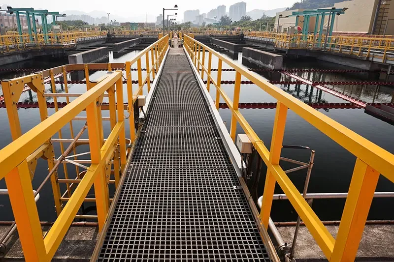
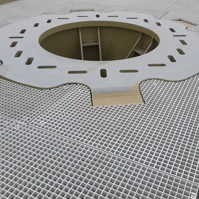
A drainage run is a system of fall, frame, opening and maintenance access. Photo: Dengtai Industry.
The Short Answer: Water Path First, Opening Second
An open FRP grating panel already lets water drain through its mesh. A large cutout is not automatically better. The first task is to trace where water enters, where it should leave and what happens below the platform. Only then can the layout show whether the project needs ordinary mesh drainage, a small pipe or cleanout penetration, a framed channel, a removable access piece or a covered surface.
This distinction prevents a common error: treating every wet area as a request to cut a hole. A hole that is not at the low point can leave the same ponding while removing structural bars and walking area.

Do Not Use Another Cutout as the Drainage Design
A supplier page may show a drain grate, a cutout around a pipe or a long trench run. Those examples do not tell you where the water should go on this platform.
The Longtime panel-layout and cutouts guide correctly starts with a dimensioned layout, support arrangement and common reference point. The Fibergrate engineering guide shows that openings interrupt the panel and require the support condition to be reviewed. Those principles are more useful than copying an opening size.
A practical drainage review keeps four questions separate:
- Does the open mesh handle normal water flow?
- Does the project need a local opening for a pipe, outlet, cleanout or retained solid?
- Does the remaining edge still have bearing and a safe walking boundary?
- Can the route below the platform accept the water and debris?
Locate the Low Point and Outlet
Mark the water source, the intended low point and the outlet. The low point may be a sump, gutter, channel or discharge zone below the platform rather than a cut through the grating.
Record the outflow level. A hole can be well formed and still retain water if the outlet is above the local floor or if the underside route is blocked. For a covered or solid-top surface, the joint, perimeter and outlet become even more important because water cannot pass through the central panel.
Trace What Happens Below the Grating
Water that passes through the mesh still has to leave the platform zone. Check:
- beams and stiffeners that collect water or block it;
- pipe racks, cable trays and equipment below;
- electrical areas or maintenance positions that must stay dry;
- debris, sludge and ice that can block a lower path;
- the discharge velocity and splash direction; and
- whether maintenance access will be obstructed by the final cut.
A drainage opening that sends water onto a cable tray is not a successful layout even if water passes through the grating.
Hand Over the Hydraulic and Environmental Inputs
The grating opening cannot be sized from a pipe diameter or a visual estimate of “enough drainage.” The project engineer needs the design rainfall, washdown flow, event duration, expected liquid volume, allowable ponding, outlet capacity and debris assumption where those conditions apply.
For a cold-climate platform, snow, ice and frozen debris can also change the available flow path. For process or chemical areas, water and spills may require collection, interception, treatment or controlled discharge. Open FRP grating does not provide containment, so a local cutout must not be used to bypass an environmental control boundary.
Our drainage layout review confirms the cut geometry, panel edge, added support and piece record. Hydraulic capacity, containment, discharge quality and permits remain with the responsible drainage and environmental design.
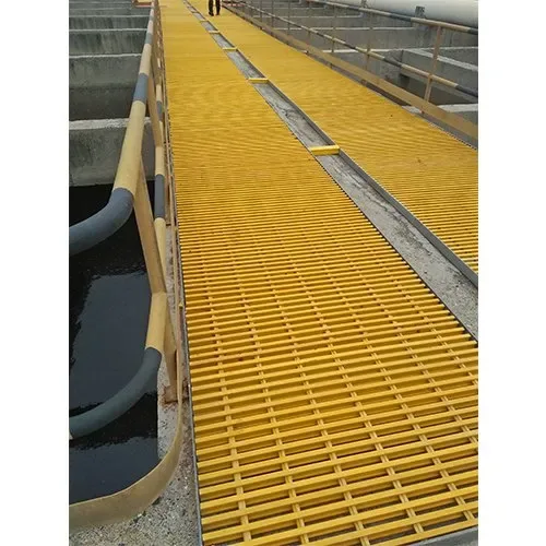
Use Mesh Openings for Water, Not Unplanned Holes
Molded and mini-mesh panels distribute many small openings across the surface. The upper mesh can reduce what falls through, but it also changes cleaning and blockage. Pultruded panels have long directional slots; their bars, cross rods and support direction still control the structural behaviour.
Do not enlarge a random area to compensate for a smaller mesh that is clogging. First identify the debris that causes the problem. The mini-mesh drainage and cleaning guide explains how to separate retained debris, cleaning access and actual openings.
Frame and Support the Remaining Edge
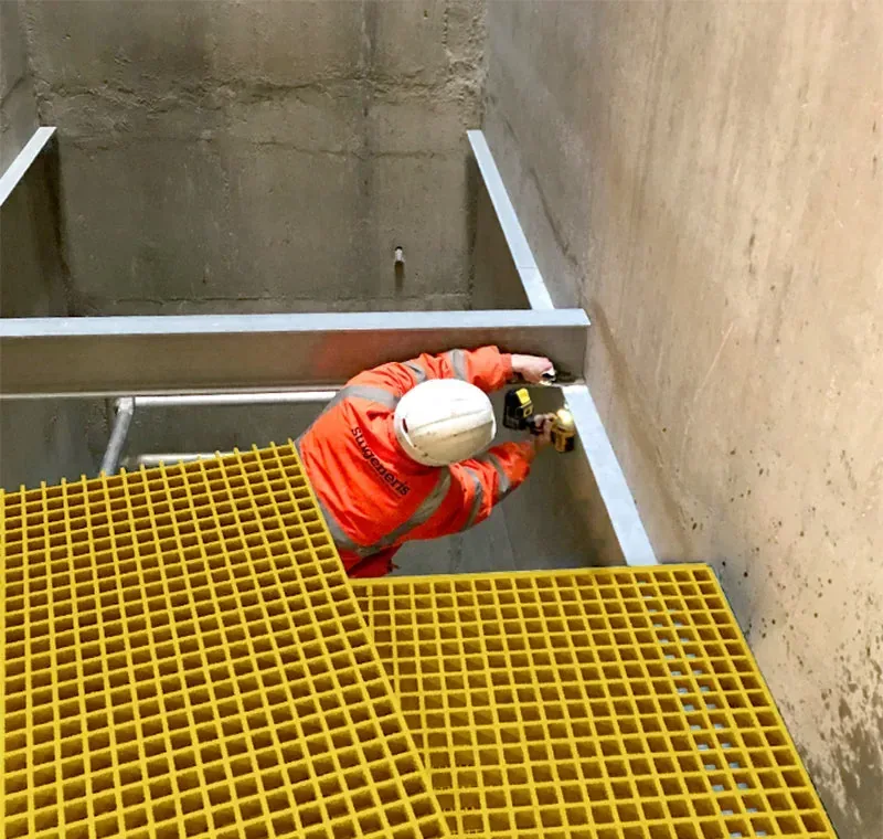
Every cut creates new edges. The remaining panel must still bear on a beam, frame, curb or added trimmer. A hole can also separate a narrow strip from the main walking area, making it difficult to support and safe to use.
Show the opening from one reference edge and dimension the finished cut, not only the pipe or obstacle. Mark the removed bearing bars or mesh, the frame beneath and the edge treatment. When the opening is near a panel joint, review the joint, opening edge and clip positions as one node.
Keep the Walking Route and Fall Boundary Visible
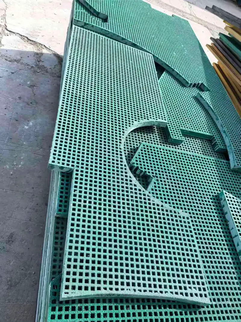
A drainage opening is also a change in the walking surface. It can create a fall-through hazard, a place where a foot or trolley catches, a narrow strip beside the opening or a route that no longer meets the needed clear width.
Mark the intended walking route and the edge protection or barrier requirement. Do not use edge sealing, a small clip or a line on the drawing as fall protection. If the opening is large enough to permit access, the project must decide whether it is guarded, covered, removable or excluded from the working area.
Plan Cleaning and Removable Pieces
The most open mesh can still block with fibers, sand, food solids, leaves or process debris. Define:
- what must be removed from above;
- which side of the panel is cleaned;
- how the cleaning water and debris leave;
- whether the opening cover is loose, clip-fixed, hinged or removable; and
- how the piece is reinstated so it cannot become a trip or fall opening.
A removable drainage piece should have its own ID, restraint and installation direction. It should not be interchangeable with a similar rectangle elsewhere on the platform.
Our Factory View
We can fabricate a controlled opening, cut the agreed edge, seal the exposed laminate, mark the piece and pack it with the matching frame or hardware scope. We can also flag an opening that leaves an unsupported strip or conflicts with a panel joint.
We do not design the platform fall, hydraulic capacity, drainage system, structural trimmer or fall protection unless those duties are included in a separate written scope. The useful output is a supported, traceable finished piece that matches the approved drainage layout.
Final Release Rule
Release a drainage opening only when the source, low point, discharge route, opening function, support edge and walking boundary agree. An open panel is a drainage medium, not a substitute for a complete water-path design.
Technical References and Limits
The Longtime FRP panel-layout guide illustrates common-reference cutouts, support coordination and piece identification. Weland’s grating planning and design page shows how layout drawings and piece identification support installation. The Fibergrate engineering guide treats openings as changes to the panel and support condition.
These references help define the fabrication and support questions. They do not establish the hydraulic capacity, slope, outlet size or fall-protection requirement for the current platform.
Drainage vocabulary
Ten Terms That Separate Water Flow From a Hole in the Grating
A cutout, mesh opening, fall, outlet and walking boundary perform different jobs.
- Surface drainage
- Water that crosses the walking surface and passes through open mesh, joints or a local opening. The path depends on the surrounding fall and outlet below.
- Drainage opening
- A cutout in the grating used for a pipe, outlet, cleanout, inspection point, object passage or another defined local function. It is not automatically a hydraulic solution.
- Low point
- The location toward which water is intended to move. It may be a gutter, sump, outlet, channel or collection area rather than a hole cut through the grating.
- Discharge route
- The path from the platform opening or mesh to the final drain. Beams, pipes, equipment and debris below can interrupt it.
- Local fall
- The slope or local depression that routes water. Grating follows its supporting structure; an opening does not create fall by itself.
- Bearing edge
- The frame, trimmer or support face beneath the remaining panel edge. Cutting a hole creates new edges that must have a defined structural condition.
- Trimmer or added frame
- A member placed around an opening to carry the remaining grating or receive a cover frame. Its need and geometry belong to the project layout.
- Debris and retention
- What must pass through the opening, what must stay above it and how the area is cleaned. Mesh size, local opening and cover format are different choices.
- Walking boundary
- The remaining accessible width, fall-through exposure and edge protection around the opening. Supporting the hole does not automatically make the walking route safe.
- Flow release
- The recorded check that the opening, frame, edge treatment and discharge route perform the agreed function without trapping water or blocking maintenance.
Drainage conditions
Which Grating Opening Actually Fits the Water Path?
Start with the source and discharge, then define the local panel cut.
| Drainage condition | First action | What the opening must not hide | Main risk |
|---|---|---|---|
| Rain or washdown through open grating | Confirm normal mesh drainage and the outlet below | An extra hole is not a substitute for missing fall | Water can hit equipment or pool on a support |
| Local pipe or outlet penetration | Locate the pipe, clearance and frame | The cut edge can remove bearing bars | The penetration may not provide the required open area |
| Cleanout or inspection access | Define removable piece and reinstatement | Access does not equal unrestricted hole size | Lifting and fall exposure |
| Linear channel or trench | Define a continuous framed run and cover layout | A short local cutout cannot replace the channel | Piece span, lifting and water retention |
| Covered or solid-top platform | Route water at joints, edges or a dedicated outlet | The cover surface may not be watertight | Ponding and blocked joints |
| Equipment drip zone | Trace discharge away from electrical or maintenance areas | A drip tray is not interchangeable with a grating opening | Splash and contamination |
| Chemical or process spill | Define containment, collection and treatment responsibility | Open grating is not a spill-containment barrier | Environmental discharge and permit breach |
Grating formats
How Open, Mini Mesh and Covered Grating Change Drainage
Open area, debris, fall and edge treatment must be reviewed together.
| Grating format | Drainage behaviour | What still needs a layout |
|---|---|---|
| Molded open mesh | Many small openings pass water across the panel | Local fall, outlet and any solid retention requirement |
| Mini mesh | Finer upper mesh passes less debris | Blockage risk, cleaning access and local opening area |
| Pultruded open grating | Directional bars create long continuous slots | Bearing direction, support lines and washdown route |
| Covered grating | The top layer closes much of the surface | Joint path, edge upstand, outlet and side sealing |
| Solid-top access cover | Water sheds around the cover unless an outlet is provided | Slope, rim, lifting and drainage boundary |
| Mixed open and covered areas | Water crosses a product transition | Transition strip, level, edge and route continuity |
Opening register
What a Platform Drainage Opening Layout Must Record
Ten fields connect the water condition to one supported and traceable finished piece.
Swipe horizontally to view all columns.
| Layout field | What to record | Why it matters |
|---|---|---|
| Water source | Rain, washdown, spill, condensation, process liquid or cleaning | Selects the expected flow and frequency |
| Low point and outlet | Coordinates and finished level of the intended discharge | Prevents a hole from fighting the actual fall |
| Surface path | Direction, fall, kerb, lane and obstruction | Shows whether water reaches the outlet |
| Subdeck route | Beams, pipes, cables, equipment and discharge target | Reveals hidden blockages and splash risks |
| Opening | Purpose, finished size, shape, clearance and reference edge | Connects the obstacle to the cut geometry |
| Support around opening | Existing member, trimmer, bearing width and fixing | Replaces the removed load path |
| Walking edge | Clear route, fall-through exposure and barrier requirement | Keeps drainage from creating a new hazard |
| Debris and cleaning | Retained object size, cleaning tool and removal route | Prevents a small drain path from blocking |
| Piece identity | Opening ID, panel ID, edge treatment and removable status | Keeps fabrication and installation aligned |
| Flow check | Approved test or observation, date and open item | Confirms the installed condition |
Readiness gates
When an FRP Grating Drainage Opening Is Ready for Fabrication
Do not cut until the water path, outlet, edge support and walking boundary agree.
Specify this if…
- The source and intended discharge point are marked.
- The difference between mesh drainage and a local cutout is understood.
- The opening has a function, dimensions and common reference.
- The remaining panel edge has a support condition.
- Walking width, falling-object risk and cleaning are reviewed.
- The water route below the platform is not obstructed.
- The design flow, allowable ponding and outlet capacity are stated where required.
- Any chemical spill, containment or treatment requirement is assigned to the responsible system.
Look elsewhere if…
- “Ponding” is being solved only by cutting a larger hole.
- The outlet is positioned without checking the fall.
- The opening removes bars without added support or a revised split.
- Fine debris will immediately block the only flow path.
- The hole becomes an unguarded fall or trip boundary.
- A local opening is expected to act as a complete hydraulic system.
Layout sequence
From Water Source to a Released Drainage Opening
Trace the water first, then locate, frame, cut and verify the local opening.
Draw rain, washdown, spill, condensation and cleaning water entry points.
Record the low point, drain or collection route and its finished level.
Check beams, pipes, equipment, electrical areas and places where debris can collect.
Separate mesh drainage, pipe clearance, cleanout, object retention and trench-cover needs.
Mark the frame, trimmer and bearing; revise the panel split if the remaining strip is impractical.
State who checks the flow, debris condition and reinstated walking route.
Platform checklist
What to Send With an FRP Grating Drainage Layout
Twelve records make the water path, opening, support and environmental boundary review usable.
- Platform plan — Dimensions, bays, walking route, equipment and changes of level.
- Water sources — Rain, washdown, spill, condensation and cleaning frequency.
- Outlet — Location, type, size, level and discharge direction.
- Surface fall — Slope, high and low points, kerbs, lane and ponding check.
- Subdeck route — Beams, pipes, trays, equipment and clearance below the opening.
- Opening schedule — ID, function, shape, dimensions, clearance and common reference.
- Support — Existing frame, trimmer, bearing surface and panel split around the opening.
- Edge condition — Cut treatment, walking boundary, protection and removable detail.
- Debris and cleaning — What passes, what is retained, cleaning method and access.
- Hydraulic basis — Design flow, event duration, allowable ponding, outlet capacity and blockage assumption.
- Environmental boundary — Spill containment, interception, treatment, discharge target and permit responsibility.
- Release — Water check, responsible person, reinstatement and drawing revision.
Opening schedule
What the Approved Drainage Opening Detail Should State
The water duty, opening, support, edge and test require one traceable record.
Request a Project Quote| Specification | Value |
|---|---|
| Opening ID | Unique reference Links the water duty, panel cut, frame and inspection. |
| Function | Drainage, pipe, cleanout, access or retention The same size does not serve all functions. |
| Location | Dimensions from one reference Do not locate from multiple local points. |
| Outlet | Position and finished level A low hole can still discharge above the collection level. |
| Removed bars | Marked on the panel Open area does not prove structural support. |
| Added support | Frame or trimmer detail The cut creates a new bearing edge. |
| Edge and route | Edge treatment plus walking boundary Sealing is not fall protection or structural support. |
| Hydraulic basis | Project flow and ponding criteria The opening is not sized from a pipe diameter alone. |
| Containment | Required system and responsible owner Open mesh is not a spill barrier. |
| Flow verification | Test method and result Record the actual installed condition. |
Drainage review
Send the Platform Plan and Water Route
Show the source, low point, outlet and support below every proposed cut.
- State what must pass and what must stay above
- Include the slope and outlet rather than only a hole size
- Show the support under the remaining panel edge
FRP Grating Drainage Opening Questions
Does open FRP grating need special drainage holes?
Can cutting a larger hole solve ponding?
Where should a drainage opening be located?
Does the opening need a frame?
Can the grating opening be used as the drain cover?
How do I keep debris from blocking the drain?
Can water discharge beside the platform instead of through a cutout?
Does edge sealing make the cut watertight?
Does open FRP grating provide spill containment?
What water-flow information should accompany the layout?
What water test should be used?
What should be included in the quotation?
This content was prepared and reviewed by Dengtai Industry’s technical and production team using the project conditions, available product data and applicable documents. Limits that require design, testing or approval are identified in the content. Content last checked: