FRP grating joint coordination
FRP Grating Panel Joints: Do They Need Support?
The answer is conditional: a joint needs support unless the specific panel, support, gap and fixing arrangement has been evaluated. A C clip can join two edges, but a clip alone never creates the support beneath them. Approve the joint from the drawing, not from the fitted clip alone.
Prepared by
Dengtai Industry
Published
·
Reviewed

Finished-piece geometry and panel joints are connected, but each still needs its own controlled detail. Photo: Dengtai Industry.
Start With the Joint, Not the Gap
A panel joint is where two delivered pieces meet. It is also where the panel edge condition, support arrangement, clip function, movement allowance and installation sequence come together. A drawing that shows only a line between two panels has not yet defined that joint.
The first useful question is not “what gap should we leave?” It is “what supports the adjoining edges, and how does each panel transfer its load into that support?” Once that path is clear, the gap, clip type and installation sequence can be reviewed against the actual product.

Keep Support and Connection as Separate Functions
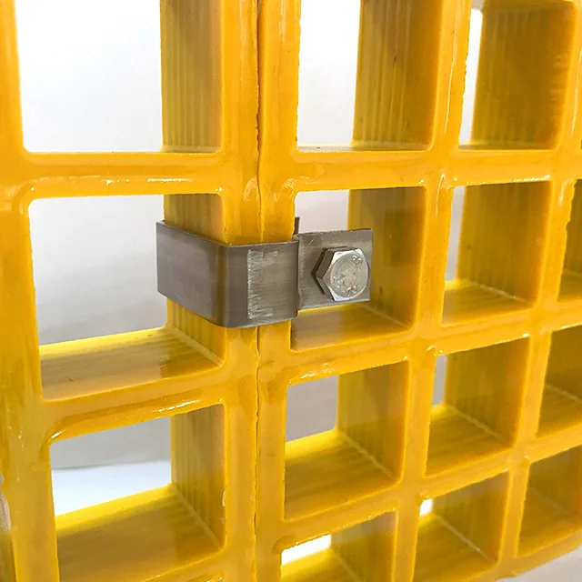
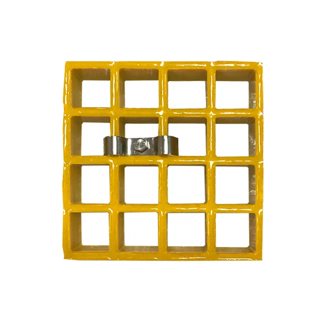
In the product family described here, M and L clips restrain a panel at a support and C clips connect adjacent panels. Those functions are distinct. The letters are not an international naming standard: another system may use an F-style abutment clip for a similar panel-to-panel task. Identify the physical function and reviewed detail before substituting one letter for another.
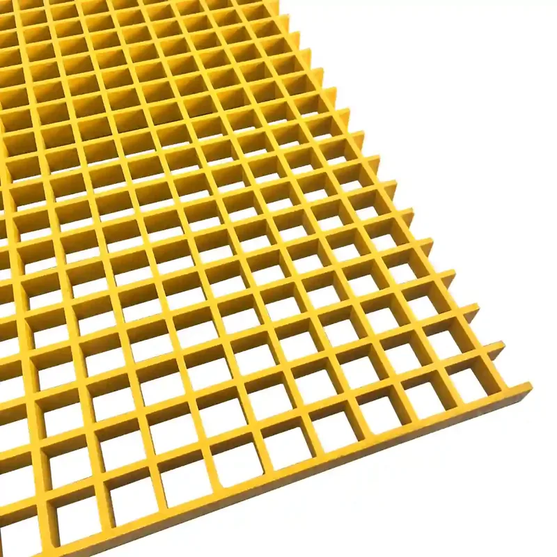
Molded grating has an integral bidirectional grid. That does not mean every edge can float between supports. The supported edges, clear span, cut edges and any design allowance for a gap still require confirmation.
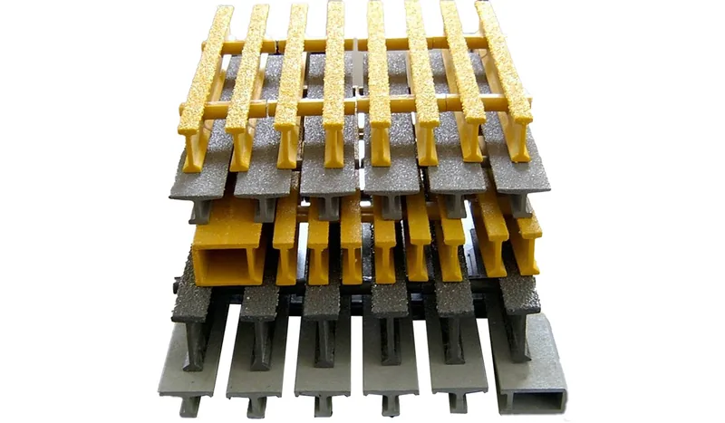
Pultruded grating has a stronger directional load path through its bearing bars. A joint may work with the bar ends near a support, but the direction and end-bearing detail must remain visible. Rotating a panel to make the rectangle fit can change that path without changing the outline.
Check the Letter, the Fit and the Fastener
A usable fixing detail controls more than the letter on the clip. It also identifies the bar or edge the clip engages, the support lip it clamps, the bolt path, the washer and nut condition, the fastener material and the access needed to install it.
For wet, coastal, chemical or otherwise corrosive service, the fastener specification needs to follow the exposure and the approved fixing system. Do not pair an FRP panel with an unspecified plated fastener just because the panels themselves are corrosion resistant.
Installation also needs a seating limit. Tightening a clip until it crushes the bar can damage resin and create a stress concentration. The correct condition is controlled engagement and snug fixing, not maximum torque. Wind uplift, vibration, removable panels and traffic at an exposed edge can require additional restraint, but those requirements belong to the project fixing schedule rather than a universal clip count.
Define the Joint Type From the Actual Detail
There are several situations that can look similar in a plan view:
- a standard panel edge bearing on a beam;
- a joint placed near, but not directly over, a structural member;
- a panel edge adjacent to an opening or change of level;
- a removable panel within a fixed frame;
- a movement interface with a designed clearance; and
- a covered assembly where base and cover joints may not align in the same way.
Each needs its own detail. A joint can be supported, but the bearing width may be inadequate. It can sit above a beam, but the pultruded bearing bars may be running the wrong way. It can be removable, but the reinstatement restraint may be undefined. The review should identify all of those conditions rather than stop at “there is a beam underneath.”
Put the Joint on the Panel and Support Drawings
The joint line should appear on both the panel layout and the support drawing. Use the same IDs for the adjoining panels and the support member. Add the joint ID so a reviewer can follow the condition through quotation, fabrication and installation.
For each joint, keep:
- the left and right panel IDs;
- the product construction and orientation;
- the support or added frame beneath the edges;
- the edge treatment and visible condition;
- the hold-down or connector requirement;
- the gap or movement allowance from the approved detail;
- the inspection method; and
- the drawing revision.
This is the same identity discipline used on the platform opening schedule and the mixed RFQ item master. A joint is a project object, not an incidental gap in the AutoCAD linework.
Do Not Turn a Common Field Rule Into a Universal Specification
Supplier guidance may show minimum hold-down patterns, joint support conditions or opening limits for a specific product family. Those details are useful starting questions, but they do not automatically transfer to another thickness, mesh, bar profile, support condition or installation environment.
Our quotation therefore asks for the product and support basis before confirming the joint detail. If the drawings do not show enough information to decide whether an edge is supported, the line remains an open technical item. The factory can fabricate and mark the approved panels; it does not silently design the support frame or infer the load path from the panel outline.
Control the Change Before Cutting
A joint may move during drafting: a panel is split to reduce handling weight, a beam moves, an opening is added or a removable access area is introduced. Any of those changes can alter finished-piece sizes, clip counts and packing.
Create a revision and update the affected joint IDs. Do not allow an old edge label to remain on a new drawing. If the change occurs after production, quarantine the affected pieces and review fit, support, inspection and packing before release.
What the Factory Can Verify
We can verify the offered panel row, cutting dimensions, edge treatment, piece marks and supplied clip or connector scope against the approved drawing. We can coordinate packing so matching panels and hardware remain identifiable.
We cannot approve the structural frame, guardrail base, anchorage, site installation sequence or a load path that is not defined by the responsible project parties. That boundary should be visible in the quotation rather than hidden in a generic installation note.
Final Joint Rule
Release a joint only when the panel edges, structural support, orientation, gap and fixing describe the same condition. A C clip confirms that the edges are connected; it does not confirm that the joint is supported.
Design References and Limits
The Fibergrate engineering guide shows how one manufacturer treats supported abutting edges, abutment clips, hold-downs and openings. The Jivial installation guide provides a useful field check on bearing direction, fastener material, clip seating, edge sealing and penetration support.
Those details are evidence of the questions a joint review must answer. Their quoted clip spacing, opening limits and fixing quantities belong to the named product systems and must not be transferred to another panel without the approved system data. Our quotation therefore uses the actual product, support layout and fixing schedule for the ordered panels.
Joint vocabulary
Ten Terms That Separate Panel Connection From Structural Support
A joint, a support, a hold-down, a connector and a gap each perform a different function.
- Panel joint
- The interface where two grating pieces meet. It may be a butt joint, a supported joint, a deliberate movement interface or another project-specific edge condition.
- Support beneath the joint
- A structural member, bearing bar, edge beam or added frame that can carry the joint condition into the supporting structure. It is different from a clip joining the panel edges.
- Butt joint
- Two panel edges placed next to each other. The size of the gap, support arrangement and edge finishing depend on product construction and the project detail.
- Hold-down clip
- In the current product family, an M, L or other clip that restrains grating to a support. Clip letters vary between suppliers, so the function must be confirmed. It does not create a support member or make an unsupported joint structural.
- C clip
- A connector fitted at adjacent panel edges in the nomenclature used here. Other suppliers may use C, F or another letter for an abutment clip. The connector joins and stabilizes the edges but does not replace the support or load path beneath the joint.
- Movement allowance
- A deliberate clearance or connection arrangement that permits agreed movement, installation tolerance, removal or thermal response. The value comes from the design, not from a generic rule.
- Bearing-bar direction
- The main spanning direction of a pultruded panel. Joint and support positions need to preserve the intended direction and continuous load path.
- Joint ID
- A stable identifier for a joint condition, linking it to the adjoining panel IDs, drawing detail, support, fixing, inspection and release record.
- Joint release
- The controlled decision that the actual support, panel edges, gap, fixing and installation condition match the approved detail and are acceptable for the next stage.
- Substitution
- A change from one panel, profile, clip, support or joint arrangement to another. It requires a new technical review and normally a new drawing revision or joint ID.
Joint conditions
Which Load Path Applies to an FRP Grating Panel Joint?
Identify the support and fixing tasks before comparing joint details.
| Joint condition | What carries the load | What the clip does | What must be confirmed |
|---|---|---|---|
| Panel edge on a support | The structural support beneath the edge | Holds the grating down at the support | Bearing width, clip fit, bolt access and edge condition |
| Butt joint between panels | The panel construction, supported edge or designed support gap | C clip may join the adjacent edges | Bar continuity, gap, movement and panel identity |
| Joint in a pultruded run | Continuous bearing bars ending near or over support | Hold-down and edge connectors as specified | Bearing direction and end support |
| Joint beside an opening | Added framing or remaining supported bars | Edge clips or hold-downs as detailed | Interrupted bars, edge treatment and support frame |
| Removable panel joint | Supporting frame or supports around the removable area | Releasable fixing or connector | Lift path, reinstatement and restraint |
| Movement interface | Project-specific structural and fixing detail | Connector or fastener selected for the movement function | Gap range, direction and maintenance check |
Product conditions
How Molded, Pultruded and Covered Panels Change the Joint Question
A shared outline does not make every product joint interchangeable.
| Product condition | Joint question | Common wrong assumption |
|---|---|---|
| Molded square mesh | Which edges are supported and whether the bidirectional grid can span the planned gap | Assuming every molded edge requires the same support condition |
| Molded rectangular mesh | Where the stronger bar direction runs across the joint | Rotating the panel because the outline still fits |
| Pultruded I/T/WT | Bearing-bar ends, panel width, direction and support under the joint | Treating cross rods as a second equal load-bearing direction |
| Mini mesh | Actual upper and lower grids, panel edge and support path | Assuming smaller top openings change the joint capacity |
| Covered grating | Base-panel joint, cover joint, interface and edge support | Joining the cover visually while leaving the base unsupported |
| Finished cut piece | Piece ID, drawing revision, final edge, orientation and intended location | Replacing the approved piece with an apparently equal offcut |
Joint register
What an FRP Grating Joint Record Must Control
Ten fields keep both panel edges, support and fixing tied to one drawing revision.
| Joint record field | Required value | Why it matters |
|---|---|---|
| Joint ID | Unique project reference such as J-01 | Keeps the same joint visible from drawing to installation |
| Adjacent piece IDs | Both panel or finished-piece marks | Prevents one edge of the joint from being changed independently |
| Product construction | Molded, pultruded, mini mesh or covered | Joint requirements depend on how the panel carries load |
| Support condition | Direct support, supported gap, added framing or designed interface | Records what carries the edge condition |
| Bearing direction | Bar run and panel orientation | Prevents a rotated pultruded piece from passing an outline check |
| Edge geometry | Straight, cut, opening-adjacent or other defined edge | The edge may need treatment or a different support arrangement |
| Gap or movement | Required clearance and permitted range | A generic gap does not prove the project detail |
| Fixing | Hold-down, connector, hardware and locations | Separates panel restraint from edge joining |
| Inspection | Bearing, edge condition, fixing and alignment | Confirms the actual joint before release |
| Responsibility | Grating supplier, frame designer, installer or other owner | Shows which interface must be approved outside the panel quote |
Joint readiness
When an FRP Grating Joint Is Ready for Fabrication
Use these gates before a panel edge, gap or fixing method is priced.
Specify this if…
- The joint position is marked against both panel IDs.
- The support condition is visible on the layout or detail drawing.
- The product construction and bearing direction are known.
- The clip functions and quantities are listed separately.
- The required gap or movement condition is stated.
- A joint inspection and release route is defined.
Look elsewhere if…
- The joint is assumed supported because a C clip is fitted.
- The joint can move after quotation without a drawing revision.
- A generic four-clips-per-panel rule is applied to every condition.
- The joint gap is copied from another project.
- A pultruded panel is rotated to fit the opening.
- The frame design and installation duty are absent from the review.
Joint examples
How Five FRP Grating Joint Conditions Become Actionable
The examples show record logic, not universal support or gap values.
| Example joint | Drawing condition | Missing information | Factory action |
|---|---|---|---|
| J-01 | M-01 meets M-02 at a support beam | Bearing width and hold-down positions not dimensioned | Mark clarification; do not release fabrication from an assumed edge |
| J-02 | P-03 meets P-04 between supports | No support drawing or bearing-bar end detail | Keep the joint open and request the frame/connection basis |
| J-03 | Finished piece F-07 forms an opening edge | Remaining bars and added frame are unresolved | Hold the opening detail before cutting the finished piece |
| J-04 | Removable panel R-02 sits within a frame | Lift method and restraint are not stated | Define removable-piece handling and reinstatement |
| J-05 | Covered assembly has aligned cover edges | Base-panel joint and interface are not shown | Check the complete assembly, not just top-side alignment |
Joint control
From Two Panel Edges to a Released Floor Joint
Identify, support, fix, inspect and carry the same joint into project records.
Give each adjoining panel or finished piece its stable ID and current drawing revision.
Show the beam, frame, curb, supported gap or other feature beneath the joint.
Check molded, pultruded, mini-mesh or covered behavior and preserve the bearing direction.
State which clips hold down, which connectors join edges and what hardware is included.
Record the required gap, movement, lift-out or reinstatement condition from the project design.
Compare support, edge, gap, fixing and alignment with the approved detail before closing the joint.
Joint boundaries
Four Rules That Stop a Joint Detail From Becoming a Hidden Guess
Support, clip function, movement and revision each require separate control.
- A joint is not a free edge — The edge of a panel reaches the end of its grid or bar run. Whether that edge can stop near a support, sit on a support or require added framing depends on the panel construction and the project detail.
- A clip is not a beam — C clips can join adjacent edges, and M or L clips can restrain panels to supports. Neither turns a joint between supports into a structural support.
- A gap is not universal — Installation clearance, movement and removal requirements vary by product, temperature, support and fixing. Do not publish one gap as the answer for every molded or pultruded joint.
- A joint change is a revision — Moving a joint can change panel sizes, cutting yield, bearing direction, clip quantities and installation sequence. Freeze the change before manufacturing and packing.
RFQ checklist
What to Send With an FRP Grating Joint Layout
Ten records make the joint review usable for engineering and production.
- Joint register — Joint IDs, adjacent piece IDs and drawing revision.
- Support plan — Beam or frame location, bearing surface and support under each joint.
- Product row — Molded or pultruded construction, mesh or bar pitch, depth and resin.
- Direction — Bearing bars, top face and orientation of every adjoining piece.
- Edge condition — Cut, molded, opening-adjacent or removable edge treatment.
- Gap — Required installation or movement gap from the approved detail.
- Hold-down — Clip type, material, bolt, quantity and support location.
- Panel connector — C clip or other joining device, material and location.
- Installation sequence — Which panel is placed first and how the joint is aligned and secured.
- Release — Inspection result, responsible person and any open item.
Joint schedule
What the Approved FRP Grating Joint Detail Should State
The final record should resolve the support and fixing condition, not just the visible gap.
Request a Project Quote| Specification | Value |
|---|---|
| Joint identity | One joint ID Both adjoining pieces should be visible on the same detail. |
| Support | Named structural member or designed interface A clip cannot replace the missing support. |
| Direction | Marked on both pieces Pultruded bearing direction and molded bar orientation stay visible. |
| Clip function | Hold-down or panel connector Do not use one quantity allowance for both tasks. |
| Gap | Approved value and tolerance Generic joint gaps are not project approvals. |
| Edge | Treatment defined by drawing Cut edges and opening-adjacent edges may not match standard panel edges. |
| Inspection | Bearing, alignment, fixing and edge Record the actual observed condition. |
| Change route | Revised joint and piece IDs A changed support or gap must not disappear into site instructions. |
Joint review
Send the Panel and Support Drawing
Include both adjoining pieces and every open support or movement condition.
- Mark both adjoining panels
- Show support beneath the joint
- Separate hold-down and joining clips
FRP Grating Panel Joint Questions
Do FRP grating panel joints always need support underneath?
Does a C clip support the joint?
Are four clips per panel enough?
Why does bearing-bar direction matter at a joint?
What gap should be left between panels?
Can a removable panel joint be unfastened without extra support?
How should a covered-grating joint be checked?
What should be included in a joint quotation request?
Can the factory approve the support structure?
When should a joint be recorded?
This content was prepared and reviewed by Dengtai Industry’s technical and production team using the project conditions, available product data and applicable documents. Limits that require design, testing or approval are identified in the content. Content last checked: