FRP grating field-change control
Field-Modified FRP Grating: Keeping Piece IDs and Positions Traceable
A field cut should not break the history of the panel. Keep the original piece ID, approved change, revised drawing, field location, measured outline, edge treatment, inspection and reinstated position in one record. A new mark without that chain is only a label, not traceability.
Prepared by
Dengtai Industry
Published
·
Reviewed

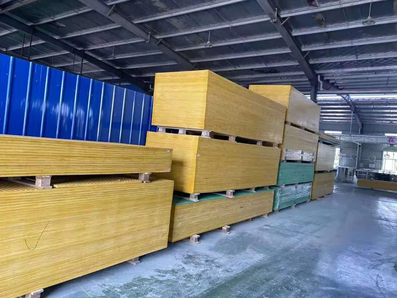
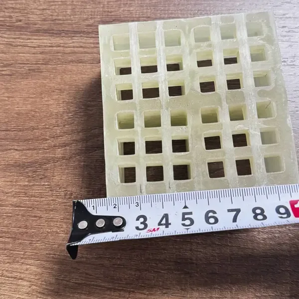
Every changed piece should remain connected to its original ID, drawing and final location. Photo: Dengtai Industry.
The Short Answer: Preserve the Old ID, Then Connect the New State
A field modification can involve a notch, an enlarged pipe opening, a shortened panel, a new removable section or a replacement after damage. The physical work may take minutes. The traceability problem lasts much longer.
If the original piece mark disappears and a new mark is written in its place, the order record, package, approved drawing and receiving inspection can no longer be connected to the installed object. If the worker remembers the location but no plan record does, the next shift cannot prove which piece belongs where.
Use one chain:
- as-shipped piece ID;
- field change ID;
- reason and field location from a common datum;
- approved drawing revision;
- field-cut method and measured result;
- edge treatment and inspection;
- reinstated location; and
- as-built release.
The original ID does not need to become the final ID in every system, but it must remain visible as the history. The changed piece may be marked as reworked, superseded or replaced under a controlled new identifier.

Trace the Problem, Not Only the New Shape
A cutout dimension alone does not explain why a piece changed. A pipe may have moved. A support may differ from the drawing. An access area may need to be removable. A damaged edge may require trimming. The reason determines which parties must review the change.
Record the field finding before proposing the cut:
- what did not fit or changed;
- which plan reference shows the location;
- which piece ID and revision were present;
- which support, joint or opening is affected;
- whether the panel is installed, removed or still packed;
- whether the issue is geometry, damage, missing information or an intentional new requirement; and
- who has authority to resolve it.
The Longtime panel layout guide makes a useful distinction between a supplied dimension and a controlled reference point. A field team may see the obstruction clearly, but the record must still locate it from a common datum so production and installation are discussing the same object.
Keep the Piece Mark Before Removing It
Before cutting or before sending a damaged panel to a workshop, capture the readable identity:
- piece mark;
- package or delivery reference;
- original order or drawing revision;
- product construction and depth;
- top face and reference edge;
- bearing-bar or mesh direction; and
- intended location.
Photograph the mark against the surrounding panel and location. If the mark will be removed by the cut, create a controlled transfer. One practical pattern is to retain the old marking in the field record while applying a new or reworked ID at a protected edge location agreed by the project. The exact method depends on the panel surface and site procedure.
Do not write the new mark on only a walking area that will be hidden or worn away before handover. Do not cover a package label without updating the package record.
Where the approved procedure allows it, a substantial identification tab with clear characters that refer to the layout drawing can be more durable than a small label on the walking surface. The tab still belongs to the physical item and must not become an unlinked second identity.
Record the Location From One Datum
“Panel near the pump” is a conversation, not a traceable location.
Use the same kind of information used for the approved panel layout:
- named plan datum or grid line;
- bay;
- support line or frame member;
- adjoining piece IDs;
- joint or opening reference;
- orientation arrow or reference edge; and
- top face when relevant.
The field location belongs to the change record before cutting, and to the reinstatement record after installation. It can change if the approved layout moves. That change should generate a new revision rather than leaving an older location attached to the piece.
Separate Location ID From Physical-Item ID
A stable location and a physical panel are not the same object.
Use a location ID for the bay, opening or installation position. That identifier remains associated with the place even when the original panel is replaced. Give the actual panel or finished piece a separate physical-item ID linked to its package, material record, drawing revision and predecessor.
This distinction matters when one location receives more than one panel over time. Reusing the old item ID because the location did not change makes a new object look like the old one. Losing the predecessor record has the opposite problem: the current panel is present, but its history cannot be reconstructed.
Reconcile the count at the same time. Let the intended active set contain N locations. A replacement may create N + 1 physical-item history records while the current active set remains N. The superseded object stays recorded separately; it is not silently deleted or added to the installed quantity.
Issue the Change as a Revision
The field team should not transmit a new outline through an informal image with no effect on the controlled drawing.
The revised drawing or change record should show:
- the superseded detail;
- the new outline or opening;
- dimensions from the common datum;
- clear opening and required clearance;
- bars or cross rods interrupted;
- bearing-bar direction or panel orientation;
- support condition around the changed edge;
- cut-edge treatment requirement; and
- piece ID and quantity affected.
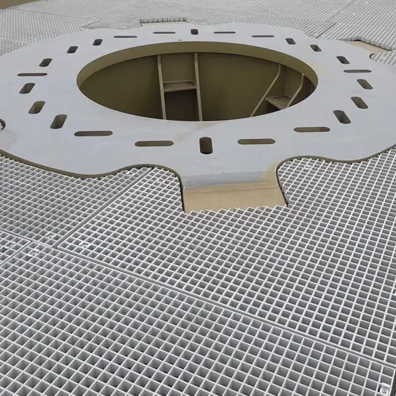
A photo can show the obstruction. A marked-up drawing can explain the geometry. Neither replaces the responsible party’s approval when the change affects structural use, support or a regulated installation.
Support the Piece During the Cut
The Bedford fabrication and installation manual highlights a practical point that is easy to lose in a field instruction: poorly supported material can shift or chip during cutting.
The work record should therefore include:
- where the piece is supported;
- how movement is restrained without crushing the product;
- which face is selected for the cut;
- tool and blade type from the product guidance;
- dust and personal-protection controls;
- cut sequence;
- operator and date; and
- responsible inspection.
This page does not replace the product-specific cutting guide. It adds traceability: the actual method and condition must be recorded against the same piece that enters the revised drawing.
Record the Measured Result and Remaining Bars
The requested dimension and the produced dimension are different facts.
After cutting, measure the actual outline and opening from the same datum. Record the bars and cross rods interrupted, the remaining support and edge condition and whether the orientation has changed.
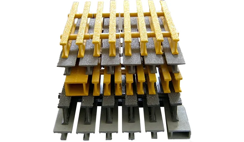
For pultruded grating, the main load path follows the bearing bars. A panel can remain rectangular after being rotated or trimmed, while the bar direction and end-bearing condition are no longer the approved detail. The traceability record should carry the direction mark into the revised drawing and the physical panel.
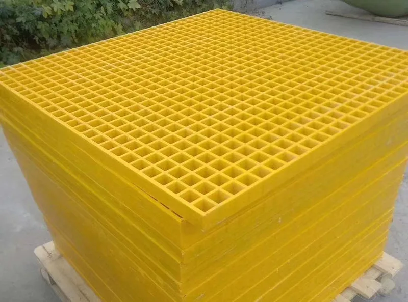
Molded grating has an integral grid, but a cut or opening can still alter the local edge, bar continuity and available support. Do not use the phrase “molded is bidirectional” as a blanket statement that the modified condition is acceptable.
The CBSI installation guidelines also connect cut quality, bearing direction and support around penetrations. These are the conditions the field record should verify on the actual piece.
Treat the Cut Edge as a Recorded Condition
The project should decide the correct cut-edge treatment for the actual product, resin and exposure. The traceability record then confirms what was actually done:
- method and material;
- area covered;
- dryness and cleanliness before treatment;
- number of applications or coverage state where relevant;
- drying or handling restriction;
- inspected appearance; and
- reference to the product-specific instruction.
Do not allow “sealed” to stand alone if the inspection cannot identify where and how the edge was treated. A sealant that was applied before the edge was clean or dry may not represent the intended condition.
The cutting and sealing guide covers the technical method. The current page links that method to the piece ID and approved revision.
Do Not Let an Offcut Inherit the Finished ID
After cutting, several objects may exist:
- the approved reworked piece;
- a useable remnant;
- scrap;
- removed bars or small fragments; and
- protective material or samples.
Only the approved finished object should retain the finished-piece identity. An offcut should receive its own quantity and disposition. If it is stored for later use, mark it as an identifiable remnant with dimensions and material history. If rejected, record scrap and prevent it from returning to the installation as an unmarked spare.
This is especially important when visually identical panels are stored on site. A label applied to an offcut can create a false replacement panel that fits but has no approved drawing history.
Know When the Change Should Return to the Factory
Some field adjustments can follow an approved field procedure. Others should go back through the factory or a qualified fabricator because the change affects product identity, controlled cutting, edge treatment or a finished piece that must be packed and shipped.
Return the decision to the controlled fabrication route when:
- the original product or piece cannot be identified;
- the revised shape removes or interrupts significant bars;
- the support condition around the change is unresolved;
- a clean, consistent cut and edge treatment cannot be achieved on site;
- the changed piece must match a pultruded bearing-bar direction;
- the replacement will be packed with other marked pieces;
- a covered or multi-layer assembly must be restored; or
- the site has no approved way to inspect and record the finished condition.
That decision is not a judgment that the installer is at fault. It is a responsibility boundary. The factory can control measurable finished-piece geometry and marks when it receives the current revision. It still cannot approve the field support, design use or installation condition from a workshop drawing alone.
The factory-versus-site cutting comparison helps make this choice before the cut, not after the offcut has already lost its identity.
Close the Chain After Reinstatement
Installation should verify:
- the correct revised piece is in the stated location;
- orientation and visible face match the change record;
- support and bearing direction have not changed;
- the joint gap and alignment are within the approved detail;
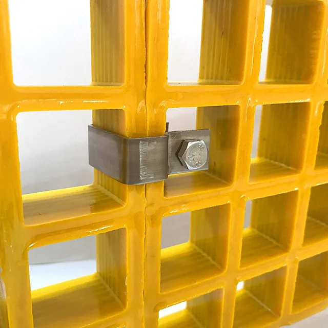
- clips or fasteners match the fixing schedule and are not used to force the panel into position;
- the cut edge remains as inspected;
- finished level and step agree with the surrounding panels; and
- the final mark or digital location record is readable.
Use the surrounding panel layout and joint details rather than treating the modified piece in isolation. The panel joint and support guide provides the separate support, gap and clip questions that apply at the new edge.
Build a Small Closeout Pack
The field closeout does not need to become an administrative project. It does need to leave the next maintenance team with the same answers:
- Which original and current IDs describe the piece?
- Which drawing revision approved the change?
- Where is the piece installed?
- What dimensions and edge treatment were actually produced?
- Which support, joint and fixing conditions were inspected?
- Which photographs show the mark, opening, contact and reinstatement?
- Who accepted the condition, and which items remain open?
Keep that pack with the platform inspection and spare-panel records. When the same location is repaired again, the team should not have to reconstruct its history from an old chat message.
Our Factory View
We can identify the offered piece, carry its original mark into the supplied fabrication record, apply the approved revised drawing and coordinate package identity for replacement or reworked pieces. We can inspect measurable geometry, supplied edge treatment and supplied marks against that record.
We cannot infer the field location from a photograph, approve a new structural purpose without the responsible design basis, or certify installation quality that we did not observe. The change record should make those responsibilities explicit.
Traceability vocabulary
Twelve Terms That Keep an FRP Grating Field Change Connected
Piece identity, approval, physical location, measured result and reinstatement each answer a different question.
- As-shipped piece ID
- The identifier on a panel or finished piece when it leaves the factory. It should link to the approved drawing revision, package, product row and intended location.
- Field change
- A request or actual operation at the installation site that alters a piece, its location, orientation, opening or edge condition after the original release.
- Superseded ID
- The original identifier retained as the history of a piece while a new revision or replacement identifier is issued. It prevents the original chain from disappearing.
- Revised drawing
- The controlled document that records the changed geometry, datum, bars affected, direction, edge treatment and approval state.
- Common datum
- A named plan reference, grid line, support edge or other fixed origin from which every field location and measured dimension is taken.
- Field location
- The bay, panel position, support, joint and opening context where the piece belongs. It is part of the identity rather than a note that can be recovered later.
- Location ID
- A stable identifier for the place that receives a panel, such as a bay or opening reference. It remains in the layout when the physical item occupying that place changes.
- Physical-item ID
- The identifier for one actual delivered, modified, replacement or retained object. Several physical items can pass through one location over the life of the platform.
- Cut result
- The measured outline actually produced, including opening size, position, remaining bars and edge condition. The requested dimension is not automatically the result.
- Offcut
- Material separated from a controlled piece during modification. It should be given a remnant or scrap disposition and must not inherit the finished-piece ID.
- Reinstatement
- Returning a changed piece, replacement or removable section into the defined location with support, orientation, joint, fixing and inspection conditions.
- As-built record
- The final identity document connecting the original and revised IDs, actual location, measured condition, approved change, inspection result and any open item.
Change controls
What Evidence Should Follow a Field-Modified FRP Grating Piece?
Match every claim about the change to a controlled record rather than an informal description.
| Field question | Controlled evidence | Not enough by itself |
|---|---|---|
| Which panel was changed? | As-shipped ID, new or superseded ID, package and drawing revision | A photograph with no readable mark |
| Where does it belong? | Common plan datum, bay and adjacent piece IDs | “Near the left of the platform” |
| Is this the current item? | Stable location ID, physical-item ID and predecessor link | Reusing the old piece mark because the location did not change |
| What changed? | Approved request plus actual measured geometry and affected bars | “Smaller cutout” written in a message |
| Who approved it? | Named decision owner and revision state | The person who operated the saw |
| Was the edge treated? | Product- and exposure-specific method plus inspection | A materials abbreviation alone |
| Can it be reinstated? | Support, orientation, joint, clip and finish-level checks | The outline fits through the space |
Product conditions
How FRP Grating Construction Changes a Field Modification Record
Directional bars, cutouts, covers and removable pieces create different traceability requirements.
| Product condition | Field-change question | Common wrong assumption |
|---|---|---|
| Molded square or rectangular panel | Cutout datum, interrupted bars, remaining edge and strong mesh direction | The original outline still controls after the opening changes |
| Pultruded panel | Bearing-bar direction, end support, rotation and reference edge | A rectangular panel can be rotated because the outline still fits |
| Mini-mesh panel | Upper and lower mesh, cut edge, opening and piece mark | Smaller top mesh makes a field cut interchangeable with a standard panel |
| Covered grating | Base-panel change, cover cut, interface and visible-edge condition | Matching the cover outline records the complete modified assembly |
| Removable panel | Lift path, reinstatement orientation and releasable fixing | A temporary removal does not need a location or fixing record |
| Offcut or remnant | Dimensions, material history and remnant or scrap disposition | Material separated from a released piece can keep the finished-piece ID |
Change register
Field Modification Traceability Record Template
These fields connect the stable location, physical-item history, approved revision and installed result.
| Change record | Required value | Why it matters |
|---|---|---|
| Original ID | As-shipped piece mark and package reference | Starts the traceable history |
| Change ID | Unique field-change reference | Connects request, drawing, work and approval |
| New status | Superseded, reworked, replacement or new ID | Prevents two identities from being used as if they were one |
| Reason | Obstacle, revised opening, fit condition or other approved cause | Explains why the original geometry is no longer current |
| Drawing revision | Current approved revision and date | Shows which dimensions control the change |
| Field location | Bay, support, adjoining IDs, joint and opening from a common datum | Keeps the piece from becoming an interchangeable rectangle |
| Location ID | Stable identifier for the installed place | Keeps the layout location stable when the physical item is replaced |
| Physical-item ID | Unique identifier for the actual object | Prevents an old and a new piece from sharing one release identity |
| Predecessor link | Superseded or replaced item reference | Connects the current item to its history |
| Active-set reconciliation | Intended active quantity plus separately recorded superseded items | Explains why delivered or historical items can exceed the current installed set |
| Requested geometry | Outline, opening, clearance and direction | Defines what should be produced |
| Measured result | Actual dimensions, position and bars affected | Records the object, not only the intention |
| Edge treatment | Method, coverage, condition and inspection | Connects the cut surface to the exposure review |
| As-built release | Inspection, reinstated location, photographs, open items and approver | Closes the chain at installation |
Change readiness
When a Field-Modified FRP Grating Piece Is Ready to Release
Identify, approve, measure, treat, inspect and reinstate before closing the record.
Specify this if…
- The original piece or readable mark can be identified.
- The changed location is shown from a common plan datum.
- The location ID remains separate from the physical-item ID.
- A responsible party has approved the new geometry or use.
- The drawing revision identifies bars, supports, edge and direction.
- The field cutting and edge-sealing method are agreed.
- The measured result can be inspected against the change.
- The reinstatement location, joint and fixing conditions are defined.
Look elsewhere if…
- A new label is issued without retaining the old ID.
- A field cut is treated as automatic structural approval.
- The location is known only from one worker's memory.
- One old mark is reused for a later physical item because the location stayed the same.
- The requested size is recorded but the measured result is not.
- A cut edge has no product- and exposure-specific treatment decision.
- An offcut is placed back as if it were the finished piece.
- No one owns design, installation and final acceptance outside the factory scope.
Field sequence
From As-Shipped Piece to As-Built Location
Preserve the old identity while the physical piece and its drawing enter a new revision.
Record the as-shipped ID, package, revision, orientation and intended location.
Match the physical piece to a bay, support, joint and opening using one datum.
State the problem, required geometry, responsible reviewer and reason.
Keep the location ID stable, assign the physical item, link its predecessor and reconcile active versus superseded counts.
Update the drawing and affected piece IDs before the first cut.
Record operator, method, actual dimensions, bars affected and edge treatment.
Check the physical piece against revision, exposure and support requirements.
Record orientation, support, joint, fixing, final location and as-built status.
Change record
What to Send With an FRP Grating Field Change
The listed records make the modification reviewable by production, engineering and installation.
- Location ID — Stable bay, opening or installation-position identifier that survives item replacement.
- Physical-item ID — Unique identifier for the actual original, modified, replacement or retained object.
- Original piece — As-shipped mark, package ID, quantity and order reference.
- Original drawing — Approved revision, orientation, visible face and intended location.
- Field finding — Obstacle or fit issue, measured condition and photograph with scale.
- Plan location — Bay, support, joint, opening and adjacent piece IDs from a common datum.
- Requested change — Required outline, opening, clearance and product direction.
- Approval — Reviewer, decision and current drawing revision.
- Cutting method — Tool, support, sequence, protection and responsible operator.
- Edge treatment — Product-specific method, material, coverage and inspection.
- Measured result — Actual geometry, bars affected, orientation and cut-edge condition.
- Offcut — Quantity, dimensions, disposition and mark or scrap status.
- Reinstatement — Support, joint, fixing, finished level and final installed location.
- History count — Intended active quantity, superseded physical items and any retained replacement history.
- Release — Photographs, inspection result, approver and any open item.
Traceability schedule
What the FRP Grating Field-Change Detail Should State
The final record connects an actual object, approved geometry and final location.
Request a Project Quote| Specification | Value |
|---|---|
| Identity basis | Location ID plus physical-item ID The location can remain stable while each actual item keeps its own history. |
| Predecessor | Replaced or superseded item reference Links the current physical item to the earlier one. |
| Location | Common datum plus bay and adjacent pieces A prose description is not a controlled installation location. |
| Approval | Named reviewer and drawing revision Operating the saw is not design approval. |
| Geometry | Requested and measured values Record the actual result, not only the site instruction. |
| Direction | Marked before removal Pultruded bars, visible face and reference edge must survive the change. |
| Edge | Defined treatment and observed condition The method depends on product, resin and exposure. |
| Offcut | Remnant or scrap disposition It does not inherit the finished-piece ID. |
| As-built | Final location and inspection status The chain closes on the installed object. |
| Count reconciliation | Active set plus history items A replacement adds a history record without necessarily increasing the active installed quantity. |
Change review
Send the Original Piece and Current Revision
Include the datum, field condition, requested change and responsible approver.
- Identify the original piece
- Show the location on one datum
- State who approved the change
FRP Grating Field Modification Traceability Questions
What does FRP grating field modification traceability mean?
Can we simply write a new panel number after cutting?
What is the difference between a location ID and a physical-item ID?
Why can the delivered item count exceed the current installed quantity?
Does a field cut change the structural approval?
Why is the installed location part of the piece identity?
How should the location be described?
What should happen to material removed from the piece?
Is a photograph enough for a change record?
When should edge treatment be recorded?
Can the factory update a site-made change?
What completes the traceability loop?
Final traceability rule
Close the Location, Item History and As-Built Record Together
A stable location, independent item identity and named approval turn a label into an auditable change record.
- Final traceability rule — Keep the location ID stable, give the physical item its own ID, link every replacement to its predecessor and close the record at the inspected as-built location.
- Reconcile history with the active set — A replacement adds a physical-item history record but does not increase the intended active set when it occupies the same location. Maintain both quantities explicitly.
- Keep design authority visible — A label, drawing revision or completed field cut does not by itself approve a new structural use, support path or load case. Name the responsible approver.
- Fabrication and marking reference — Bedford supports adequate cutting support and controlled cut marking. Open the Bedford fabrication and installation manual
- Cutting and support reference — CBSI links cut quality, edge sealing, bearing direction and support around penetrations. Open the CBSI installation guidelines
- Panel ID and revision reference — Longtime connects a common datum, piece marks, orientation, packing labels and drawing revisions. Open the Longtime panel layout and cutout guide
- Location versus physical-item reference — High-Mat illustrates stable location records, predecessor links and active-versus-superseded count reconciliation. Open the High-Mat panel identification guide
This content was prepared and reviewed by Dengtai Industry’s technical and production team using the project conditions, available product data and applicable documents. Limits that require design, testing or approval are identified in the content. Content last checked: