Riser service-opening control
Riser Flooring Cutouts: Control Services and Openings
A riser opening starts with the full service and maintenance envelope, not a pipe diameter. Coordinate its purpose, datum, panel joint, interrupted bars, added support and fixed or removable status on one drawing revision.
Prepared by
Dengtai Industry
Published
·
Reviewed

An equipment platform reference. Riser cutouts require service, support and maintenance information on one plan. Photo: Dengtai Industry.
A riser flooring cutout is controlled only when the service, the opening and the interrupted panel are described on one current drawing. The pipe or duct is one object inside that record. The opening may also need space for a flange, insulation, a valve operator, tools, equipment removal, future cables or another maintenance action.
This guide is for a building service shaft or riser where FRP floor grating provides access around MEP services. It is not a guide to domestic stair risers or to cutting an arbitrary hole in a floor panel. The GRP riser grating overview explains the complete shaft layout. This page concentrates on the opening register and the information needed before factory cutting.

Start With the Service and Maintenance Envelope
Measure the service object and the clearance needed to work on it. For a pipe, record the outside diameter, flange envelope, insulation and any sleeve. For a duct or cable tray, record both outer dimensions and the future cable allowance. A valve may need a hand, a tool, a viewing line and enough room to remove a spindle or instrument.
Two services with the same pipe diameter can therefore need different openings. One may pass straight through the floor with fixed insulation. Another may terminate in a valve that must be reached regularly, or include a flange that has to be lifted through the opening. The schedule should explain what the person or equipment must do, not only what currently occupies space.
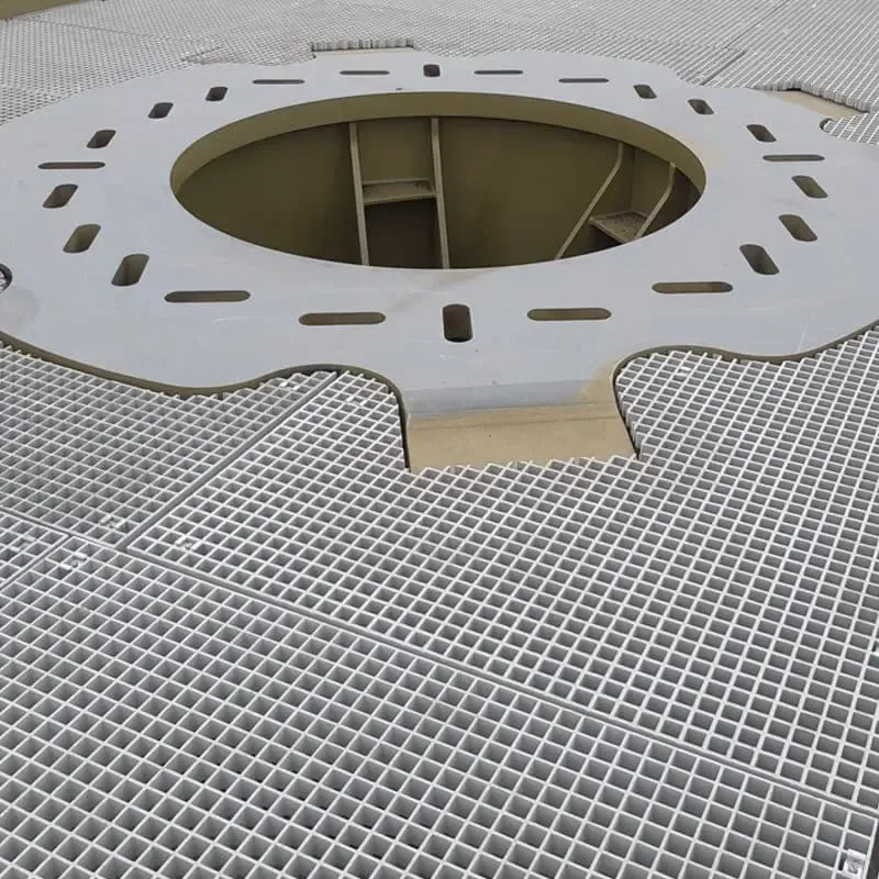
Give Every Opening One Clear Job
Use opening types that match the actual task. A fixed pipe penetration has a different geometry and approval basis from a lift-out inspection panel. A future cable reserve is not the same as a temporary construction void. If one opening serves several jobs, state all of them so the largest maintenance and removal envelope is not lost.
Our factory review treats the opening register as a release document. It records a unique opening ID, the service ID, the opening purpose, whether it is fixed or removable, and the owner of the maintenance action. These fields make it possible to compare the finished grating with the drawing without relying on a site description such as “the opening near the large pipe.”
A service opening is also different from the repeating mesh opening in the grating. A pipe cutout may be one large local opening, while the panel mesh is selected for walking support, drainage and the risk of objects falling into the shaft. If people or equipment operate below, compare mini-mesh and solid-top options with the actual object size, ventilation, cleaning and dropped-object requirement. The mini-mesh guide and mini-mesh versus solid-top comparison keep those decisions separate from the cutout size.
Overlay Openings With Panel Joints and Supports
The opening schedule must use the same datum as the panel layout. Give X and Y coordinates from the shaft grid, a wall face or another agreed reference. Show panel boundaries, the grating bar direction and every support line. An opening in the middle of a continuous field can behave differently from one beside a panel joint, free edge or support.
For molded grating, the opening removes members from an integral grid. For pultruded grating, the bearing-bar direction and support span are especially important because a rotated piece can look correct from above while the load direction has changed. The molded cutout guide and load and span guidance explain the local review. The customer should not expect a single opening-size rule to cover every product, span and load.
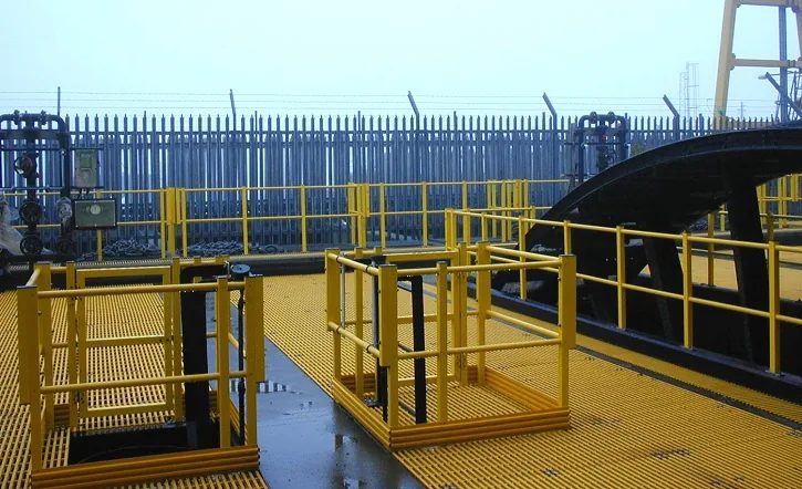
Add Load, Temporary Duty and Deflection
An opening can pass the geometric check and still fail the load-path review. Record the walking duty, concentrated or wheel load, equipment and tool loads, and any temporary construction activity that will use the riser floor. Then compare the affected clear span, bearing, remaining bars, support arrangement and deflection limit with the actual product configuration.
A standard panel load table may no longer apply once the layout or support condition has changed. High-Mat’s cutout review makes this distinction between cutting the panel and proving the finished local load path. Use the load and span guide to collect the project inputs; only the responsible engineer can determine whether the finished opening and support arrangement are adequate.
Separate Added Support From Edge Sealing and Fixings
Where the interrupted grid needs a load path, added support may take the form of a perimeter frame, trimmer, bearer or another project-designed member. That support must connect to the surrounding structural system. Adding a steel trim or a panel joining clip does not by itself establish bearing.
Avoid using the pipe, duct or column as an accidental support for the grating. A process pipe may vibrate, expand or need removal, and its support design belongs to the services engineer. A structural column can carry building loads, but the grating needs a project-defined clearance and an independent support arrangement around the column. The pipe and column cutout guide treats those obstructions separately.
The factory can cut and identify the approved panel pieces. We can review the opening register for missing fields and keep the cut list tied to the released revision. Structural design of added frames, anchors, support steelwork and fire-stopping remains a responsible-project scope unless a wider written supply is agreed.
The support method also affects future service changes. A cast-in frame, formed concrete rebate, top-fixed perimeter angle and post-fixed internal support do not leave the same ability to revise an opening or remove a panel later. Dura Composites’ riser manual explicitly warns that grating cast directly into concrete can be difficult to adapt when services are installed later. Decide the construction method with the opening-control strategy, not after the slab is complete.
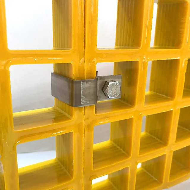
Define Fixed Openings and Removable Access Zones
Every opening also needs an access class. A fixed penetration remains part of the installed floor. A removable piece is designed to be released, lifted or hinged. It needs a manageable mass, a lift route, an orientation mark and a reinstatement sequence. An unfastened piece is not a controlled access panel.
Where the panel can be open, the project must define temporary fall protection, access control, lighting, tools and storage. Open grating is not automatically a barrier around the void. The removable riser panel sequence expands this operational state without giving generic safety approvals.
Separate Reaction to Fire, Fire Resistance and Compartmentation
These are three different questions. Reaction to fire describes how the product contributes to fire under defined test conditions. Fire resistance describes the performance of an element or assembly over a required period. Compartmentation concerns the continuity of the building’s fire-resisting separation. An open grating access floor does not automatically provide the second or third function.
Vital GRP’s RiserDeck specification guide separates the access deck from the shaft enclosure and fire-stopping interfaces. We apply the same boundary: state the required performance and tested product scope, then coordinate the fire-stopping system around each service. The FRP grating fire-rating guide explains why a resin name or material description is not enough by itself.
Release One Opening Register to Cutting
Before cutting, reconcile the MEP service schedule, panel layout, support drawing and access list. Check that every opening has one ID and one position, and that the drawing revision is current. If a pipe has moved, a new opening has been added or a panel has become removable, the register and piece list must change together.
Fabrication should follow the released register, not a photograph of the shaft. Edge treatment, piece marks, top-face orientation and packing group are recorded with the cut. When changes occur after installation, the same record remains the basis for a controlled field modification. The field-change traceability guide explains how to keep the original and revised piece identities connected.
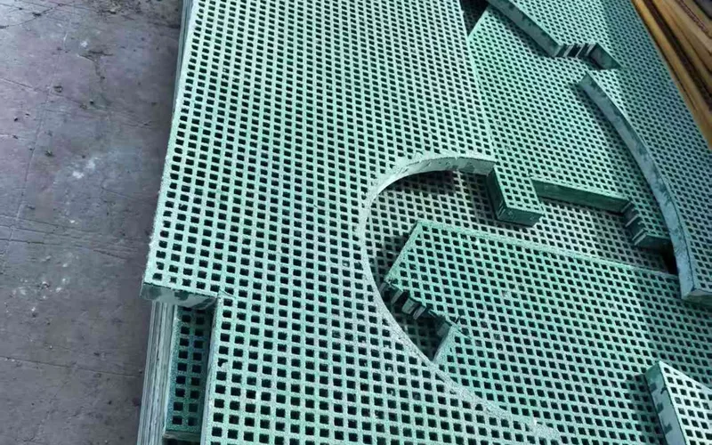
Our Factory View: The Opening Register Is the Interface
The most useful customer package is not a set of photographs with “cut around the pipes.” It is a shaft plan with an opening register, panel piece list and support layout on the same revision. From that package we can identify which pieces are fixed, which lift, where the end faces are, how the pieces are marked and what information remains missing.
We would rather stop at a marked hold point than fabricate a visually plausible opening that has no service envelope or support owner. That protects the installer from discovering a conflict in the shaft, and it protects the owner from accepting a cutout whose structural and maintenance basis was never recorded.
Before fabrication
Riser Flooring Opening Terms
- Service envelope
- The full space occupied or reached by a service, including pipe or duct size, flanges, insulation, tools, movement and any agreed future reserve.
- Opening purpose
- The reason the material is removed: service penetration, valve access, inspection, equipment removal, future capacity or another defined action.
- Common datum
- A named shaft grid, wall face, column line or support edge from which both the services and every grating opening are located.
- Interrupted bar
- A molded bar or pultruded section removed by the opening. Its location and remaining load path must be reviewed; sealing the cut does not restore it.
- Added support
- A separate frame, trimmer, bearer or support member used where the project design needs a load path around an opening. It is not created by a clip.
- Fixed opening
- A permanent penetration or access void that remains part of the riser layout during normal operation.
- Removable access zone
- A panel or section intended to be released for maintenance. It needs its own identity, handling route, open-state control and reinstatement record.
- Released revision
- The approved drawing and schedule state from which fabrication may proceed. A later service move or bar-direction change requires a new revision.
Release check
When an Opening Is Ready for Fabrication Review
Specify this if…
- Every service has a size, position, datum and maintenance envelope.
- The reason for each opening and whether it is fixed or removable are stated.
- Panel joints, bar direction and supports are visible on the same plan.
- Interrupted bars and any required added support are identified.
- The surrounding structure and support responsibility are named.
- The approved revision can be frozen before cutting.
Look elsewhere if…
- The opening is dimensioned from pipe OD alone.
- Services and grating are on drawings without a common datum.
- Several trades are still moving pipes without revision control.
- An opening lands on a support or joint but the layout has not changed.
- A fastener or edge sealer is expected to restore a removed bar.
- An open access panel is expected to remain protected without a project plan.
Opening purpose
Classify Openings by the Job They Perform
| Opening job | Required envelope | Release question |
|---|---|---|
| Pipe penetration | Pipe, flange, insulation, movement and service clearance | Does the opening preserve the walking route and local support path? |
| Duct or cable tray | Rectangular envelope, future cable capacity, tray support and access | Are both axes and corner details defined from a common datum? |
| Valve or instrument access | Hand, tool, viewing direction and maintenance posture | Does removing or reaching the panel match the actual maintenance action? |
| Equipment lift-out | Installed and removal envelopes, lift direction, temporary support and route | Can the complete item pass and can the floor be restored? |
| Future service reserve | Planned pipe or cable growth, owner and permitted future modification | Is the reserve a designed opening rather than an uncontrolled later cut? |
| Construction or inspection cover | Temporary opening, access control, cover or barrier and removal procedure | Is the temporary state explicitly separate from final riser use? |
Drawing record
Fields for a Riser Service Opening Register
| Register field | What to record | Why it matters |
|---|---|---|
| Shaft and revision | Shaft ID, floor, drawing number and approved revision | Prevents a cutout from carrying a superseded layout |
| Service ID and type | Pipe, duct, tray, valve or equipment; service tag and drawing reference | Connects the opening to the actual MEP object |
| Service envelope | OD or outer dimensions, flange, insulation, tools and movement | Defines the required space beyond the pipe body |
| Opening purpose | Penetration, access, removal, inspection, future reserve or temporary use | Explains why the shape and clearance are needed |
| Datum | Named grid or edge with X and Y dimensions | Keeps factory coordinates and site coordinates aligned |
| Panel layout | Panel ID, joint, bar direction and finish side | Shows which piece and load path the opening affects |
| Interrupted bars | Bar IDs, remaining strip and distance to support or free edge | Makes the structural support question visible |
| Support and owner | Required frame, trimmer or bearer and responsible designer | Prevents the factory from inventing a structural repair |
| Fixed or removable | Access piece ID, mass, lift route and open-state responsibility | Links the cutout to maintenance sequencing |
| Evidence | Approved drawing, cut list, inspection record and change references | Gives the factory and installer one release basis |
Seven-step control
From MEP Layout to Released Riser Pieces
Agree the shaft grid, floor level, wall faces, columns and drawing revision.
Record every pipe, duct, cable route, valve and planned future service.
Add flanges, insulation, tools, movement and equipment removal space.
State whether it serves penetration, access, inspection, removal or future reserve.
Show opening positions against joints, supports, bar direction and walking routes.
Identify interrupted bars and name the added support and responsible party.
Freeze the revision, piece IDs, edge treatment, access status and inspection criteria.
Before cutting
Riser Flooring Cutout Checklist
- Current shaft drawing — Plan, sections, floor level and surrounding structure use one revision.
- Complete service schedule — Every service has an ID, type, envelope and coordinate.
- Maintenance route included — Tool, reach, lift, inspection and equipment removal needs are shown.
- Opening purpose stated — Penetration, access, future reserve and temporary use are not mixed.
- Panel and bar direction shown — The affected piece and interrupted members are identifiable.
- Added support defined — A frame, trimmer, bearer or other member is shown where required.
- Support owner named — Structural design and approval responsibility are explicit.
- Edge treatment specified — Cut-edge sealing or coating is stated without claiming structural restoration.
- Access status defined — Each opening is fixed, lift-out, hinged, covered or temporary.
- Release record complete — Drawing, piece schedule, inspection and acceptance owner agree.
Engineering boundary
What a Riser Cutout Does Not Prove

A cutout is not a support frame
Removing panel material does not create the added frame or load path a free edge may need.
Edge sealing is not bar replacement
Cut-edge protection helps the exposed composite; it does not rebuild interrupted load-carrying members.
A grating floor is not a fire seal
Open grating does not close a fire, smoke, acoustic or water boundary without a separate designed system.
A service drawing is not approval
The opening record must still identify the support designer, finished revision and acceptance owner.
Opening review
Send the Service Schedule and Riser Plan
- Molded and pultruded grating produced in house
- Full panels or factory cut-to-size pieces
- No fixed minimum order quantity
Riser Flooring Cutout Questions
How large should a riser flooring cutout be?
Is a pipe outside diameter enough for the opening schedule?
Why should the service schedule use the same datum as the grating layout?
Does every cutout need added support?
Can cut edges be sealed and left without support?
Can an opening be used as temporary fall protection?
What if a new pipe is added after the riser is installed?
This content was prepared and reviewed by Dengtai Industry’s technical and production team using the project conditions, available product data and applicable documents. Limits that require design, testing or approval are identified in the content. Content last checked: