Riser grating cutout guide
GRP Riser Grating Cutouts: Pipes, Supports and Removable Access
A service opening is not just a circle around a pipe. Coordinate the service envelope, panel joint, interrupted bars, added support, removable section and maintenance sequence on one drawing before riser grating is fabricated.
Prepared by
Dengtai Industry
Published
·
Reviewed

A service platform around pipework. A riser drawing needs equipment, movement and support on the same plan. Photo: Dengtai Industry.
Riser opening terms
Ten Terms That Turn a Pipe Route Into a Fabricable Panel
Service geometry, support, access and the open condition all belong to the same design.
- Riser floor
- The grating surface installed at a service shaft level to create an accessible walking plane while allowing vertical services and maintenance access.
- Service envelope
- The space occupied by a pipe, duct, cable tray or valve during normal operation and service, including flanges, insulation, tools and movement where relevant.
- Cutout
- Material removed from a grating piece to pass or reach a service. The cutout boundary is not automatically the same as the service outside diameter.
- Opening datum
- The fixed line or grid from which an opening location is measured. Pipe centres, shaft walls, structural columns and panel joints must be tied to the same revision.
- Interrupted bar
- A molded bar or pultruded bearing member removed by an opening. Its remaining end condition and effect on the load path require review.
- Support zone
- The perimeter frame, intermediate beam, bracket or edge detail that carries the grating around the shaft wall and each opening.
- Fixed panel
- A grating piece intended to remain in place during normal operation. It still needs a distinct ID because its direction, shape, top face and fixing may differ from nearby pieces.
- Removable access panel
- A piece designed to be released, lifted or hinged so a person can reach, inspect or remove equipment below. Its mass, route, restraint and reinstatement are part of the design.
- Open condition
- The state in which a panel or cover has been removed. Temporary fall exposure, tools, removed parts, lighting and access control have to be addressed by the project.
- Shaft boundary system
- A separate fire, smoke, acoustic, water or pressure boundary where required. A grating floor may interface with it but does not become a sealed boundary by description alone.
Opening types
Six Riser Cutouts With Different Maintenance Demands
The service and the task decide how much floor is removed and how it is supported.
| Opening type | Typical task | What the riser drawing must show |
|---|---|---|
| Pipe penetration | Pass a pipe or insulated pipe through the floor | Pipe, flange and insulation envelope; position; gap; edge and support |
| Duct or cable tray | Pass a rectangular service or provide clearance for cables | Envelope, route, future capacity, tray support and a safe walking edge |
| Valve or instrument access | Reach, view, operate or inspect equipment | Tool and hand space, approach direction and position within the walking route |
| Pump or fitting removal | Lift or withdraw equipment through the floor | Full movement path, temporary support, piece size and route for the removed item |
| Inspection hatch | Look into or reach the shaft below | Opening size, cover bearing, lift/restraint, storage and reinstatement |
| Future service provision | Allow later cables or pipe without reworking the entire floor | Planned reserve, removal panel, trim detail and who controls the future change |
Installation method
Five Ways a GRP Riser Floor Can Be Supported
The timing and condition of the shaft structure decide which support route can be coordinated.
| Support method | When it generally fits | Drawing and site inputs | Project boundary |
|---|---|---|---|
| Cast-in frame or module | The riser floor is coordinated before the floor slab is cast | Slab opening, module dimensions, frame level, anchors and service datum | Concrete design, pour sequence and final surveyed position |
| Formed rebate | The slab provides a designed ledge for the grating or its frame | Rebate width, depth, level, edge condition and bearing surface | Structural adequacy of the surrounding slab and loaded bearing width |
| Top-fixed frame or angle | A frame can be fixed onto the finished floor or opening edge | Frame section, anchors, floor material, finished level and fixing access | Anchor design, edge distance, structural approval and level or trip transitions |
| Retrofit support inside the shaft | An existing building or late riser scope needs a new internal shelf | Wall or substrate type, bracket layout, bearing, access and temporary exposure | Structural fixing design, construction-stage safety and inspection access |
| Prefabricated support module | Repeated shafts or modular construction justify factory coordination | Module size, hoisting, adjustment, services and interface to slab or walls | Structural connection, installation sequence and change control |
Panel choice
Matching Riser Grating Format to the Actual Access Duty
Open area, dropped-object control, handling, span and fire requirements can pull in different directions.
| Riser piece option | Primary benefit | Trade-off to check | Suitable starting point |
|---|---|---|---|
| Standard open molded grating | Ventilation, water passage, light and relatively low mass | Larger openings and more visibility below | General service access where dropped small items and extreme spans are not governing |
| Mini mesh grating | Smaller upper opening for tools and fixings | More debris retention, less open area and more mass | Walked access above services where dropped objects are a practical concern |
| Solid-top or covered grating | Reduced visibility below and greater object containment | Added mass, joint and drainage questions | Service zones that need a more closed walking surface while remaining removable |
| Pultruded grating | Clear directional load path where the support layout allows it | Bearing direction must remain correct through every opening and rotated piece | Defined one-way spans and a coordinated support grid |
| Fire-performance direction | A resin direction can be assessed where fire or smoke is an acceptance criterion | Product-specific test scope and boundary interfaces still govern | Projects with a stated fire performance requirement |
Coordinated schedule
What a GRP Riser Grating Drawing Must Show
Eight fields keep services, supports and finished pieces on one revision.
| Drawing field | Required information | Why it controls fabrication |
|---|---|---|
| Shaft boundary | Wall and floor opening, columns, level and surrounding structure | Defines the piece outline and perimeter bearing condition |
| Service schedule | Service ID, type, outside size, flange or insulation and future reserve | Determines the service envelope and the area removed from the mesh |
| Datum | Shaft grid, pipe centres, wall offsets and drawing revision | Locates every opening consistently in the factory and on site |
| Panel joint | Joint lines, piece sizes and bar direction | Prevents an opening from landing unpredictably at a joint or support |
| Support | Perimeter frame, intermediate supports, bearing width and added frame | Shows how interrupted bars and walking areas reach structure |
| Access class | Fixed, lift-out, hinged or cover piece with mass and lift direction | Makes handling and reinstatement part of fabrication |
| Environment | Moisture, temperature, chemical, electrical, fire and cleaning requirements | Guides resin, surface, hardware and interface questions |
| Evidence | Required load, material, fire, inspection or shaft-boundary documents | Matches the release package to the actual acceptance basis |
Coordination readiness
When a Riser Grating Layout Is Ready to Fabricate
Use these gates to find the assumptions that would otherwise move to site.
Specify this if…
- Every service has a size, position and maintenance envelope on the same plan.
- Panel joints, bar direction, supports and openings can be seen together.
- Removable pieces have a safe mass, lift route and reinstatement sequence.
- The shaft environment and any fire, electrical or water boundary are stated.
- The drawing can show which bars or support members are interrupted.
- The required evidence and supply scope are clear.
Look elsewhere if…
- Cutouts are dimensioned from pipe diameters alone.
- Services are shown on one drawing and the grating on another with no common datum.
- The site intends to cut around structural supports without a coordinated review.
- A large opening is left without a support or frame decision.
- Removable panels have no piece size, lift point or storage plan.
- A grating floor is expected to serve as a watertight, smoke or fire seal without a separate system.
The Pipe Is Only One Part of the Opening
A riser shaft drawing often shows the installed pipe and a note such as “cut around.” That note leaves the most important decisions unfinished. The dropped grating has to pass the flange, insulation or cable capacity. A valve may need to be reached with a wrench. A motor or fitting may have to rise through the floor. A future cable may need reserve room. The opening must accommodate the service envelope, not only the current outside diameter.
Start with one coordinated plan. Put the shaft walls, columns, floor level, pipe and duct centres, panel joints, supports and maintenance areas on the same grid. Use one drawing revision. When the services and the grating are on separate sheets, a small service move can silently relocate an opening onto a beam or a panel edge.
The plan should identify what must be accessible through the floor and what only needs to pass through it. A cable passing upward and a valve that must be operated every month have different opening requirements even if their nominal widths are the same.

Mark the Maintenance Action, Not Just the Obstruction
For each service area, write down the task:
- inspect a gauge or joint;
- turn or service a valve;
- remove a flange or fitting;
- pull a cable or add a future circuit;
- lift a pump or motor part;
- clean around a pipe; or
- use the floor as part of a safe access route.
Then draw the space needed for that task. Hands, tools, temporary parts, a replacement gasket and the direction of withdrawal can all increase the opening envelope. A pipe that merely passes through the floor may allow a split trim piece around an existing service. A valve that has to be operated from above may need a larger fixed opening or a separately removable panel nearby.
The walking route also stays visible. An opening that suits the maintenance action but leaves only a narrow, unsupported strip for the operator can make the floor less safe and harder to use.
Keep Panel Joints Away From Unplanned Conflicts
Panel size, bar direction and support spacing can usually be adjusted early. Once an opening falls on a joint, the shop has to make a series of new decisions: which piece loses material, how the remaining edges are supported and whether a removable service box is better than a set of small openings.
For a dense cluster of pipes and cables, one larger coordinated service bay is often easier to handle than many narrow holes. The opening can have a frame and a set of smaller cover pieces around the services. This can preserve a cleaner walking route and make later service additions possible. The alternative may be a floor filled with irregular cuts and isolated short bars.
For pultruded grating, the bearing direction is especially important. A large opening can remove a primary bearing member, while a nearby cross rod is not a substitute beam. For molded grating, the mesh provides two-direction paths, but cutting still interrupts the local grid. In either case, the opening detail must be visible against the actual bar layout.
The molded grating cutout guide explains the local effects around an opening. The broader platform cutout guide provides the finished-piece schedule method for larger equipment areas.
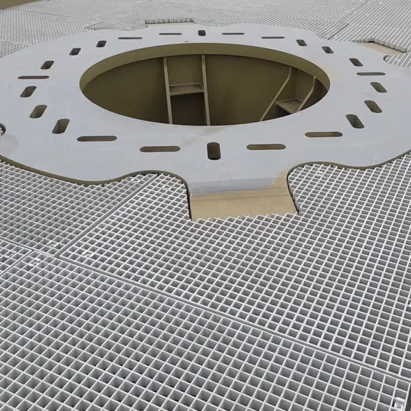
Support Around the Opening Is a Separate Decision
The grating quotation can describe the cut panel and its edge. It cannot assume that an opening is self-supporting because the remaining perimeter looks wide. The project drawing should show:
- the bearing edge at the shaft wall;
- any intermediate support beams;
- the direction of the grating bars;
- how each opening interrupts those bars;
- the frame, trim, bearer or transfer member around the cut; and
- how the removable piece bears when it is closed.
A small trim may finish the edge but may not carry the floor reaction. An added angle, channel, bracket or frame may be suitable in one detail and inadequate in another. The project engineer should approve the support configuration. We can review whether the drawing provides a coherent support boundary for the panel pieces we are asked to fabricate.
The support layout also determines handling. If a fixed perimeter frame and an intermediate beam divide the shaft into four bays, the removable piece can be one bay rather than a full-width panel. That can reduce mass and provide a clear route without removing the entire walking surface.
Choose the Support Method While the Shaft Can Still Change
The same grating panel can be supported by a cast-in frame, a formed concrete rebate, a top-fixed angle, an internal retrofit shelf or a prefabricated module. These are not interchangeable descriptions. They differ in who designs the connection, when the work happens, how the final level is adjusted and what site access is available.
For a new build, the best opportunity is usually before the slab is cast. The frame or module position, fixings, finished floor datum and service reserves can be coordinated with the concrete and MEP packages. For a late or refurbishment scope, a top-fixed or internal retrofit route may avoid major concrete work, but it introduces anchor design, edge distance, local bearing and construction access that must be checked.
Ask the project engineer to name the method on the drawing. We can fabricate grating pieces and the agreed frame or cut components, but the method still has to fit the structure and be approved by the responsible designer. A panel quotation without a support method is not a complete riser solution.
Define the Open and Closed Conditions
A removable riser panel has two states. In the closed state, it needs a stable bearing seat, a controlled position and a fixing method that returns it to the same place. In the open state, the project needs to manage temporary fall exposure, tools, removed parts, lighting and the route to the service.
Create a short sequence:
- Identify the piece by its drawing mark.
- Release the correct clips, bolts or hinges.
- Lift the piece from the designated point and direction.
- Place it in a stable storage position outside the traffic route.
- Perform the maintenance while the temporary edge is protected.
- Refit the piece onto the intended bearing and fixing positions.
- Check that all restraints are engaged before reopening the area.
The sequence is not a substitute for site safety planning. It is a test of whether the product can actually be maintained. If the piece is too heavy, cannot be reached, or requires removing an adjacent guardrail, the factory layout should be revisited before cutting.
Plan the Construction Stage, Not Only the Finished Floor
Competitor systems rightly emphasise that a riser void exists during construction, not only after handover. The permanent grating may be installed level by level as the building rises, or the opening may need a temporary cover until the final frame and services are ready. That decision belongs in the schedule.
At each stage, identify who controls the opening, what temporary guarding or covering is provided, how materials can be lifted without landing on the services below, and how later trades will open or remove pieces. If the permanent panel is installed early, protect its surface, labels and cut edges. If it arrives late, the temporary covering must not be mistaken for the final structural or fire-rated floor.
The project also needs a revision rule. A pipe that moves after slab casting can change the opening, support, removable panel and fire-stop interface. Reissue the coordinated drawing and purchase schedule instead of sending an informal site measurement that cannot be traced.
Coordinate Fire, Water and Electrical Boundaries
GRP is non-conductive and can be appropriate around electrical services, but that does not remove the need for clearances, isolation, arc protection and the electrical designer’s requirements. It also does not make an open grating floor a sealed barrier.
If the shaft requires fire stopping, smoke control, acoustic separation or water exclusion, those systems need their own design and evidence. The grating can provide a support or interface around the fire stop, cable tray or pipe, but the opening must not be described as sealed unless a tested assembly supports that statement.
Include these interfaces on the same drawing where possible. A fire-stop installer may need access and a supporting substrate around a bundle of services. A water-management detail may require a slope or upstand. Deciding those items after the grating is cut can lead to site modifications that are difficult to inspect.
Where fire performance is a stated criterion, start with the project’s required test scope rather than a resin name. The FRP grating fire-rating guide explains how flame spread, smoke or structural fire requirements may need different evidence. The phenolic grating guide provides the product direction for projects that adopt that acceptance route. Neither page replaces the fire-stop design for the shaft opening.
Cut Edges, Drilling and Piece Identity
Factory cutting gives the project an opportunity to repeat the approved geometry and apply the specified edge treatment. Site cutting may still be needed, so the specification should state how the edge is to be prepared and inspected.
The shop drawing should mark every fixed and removable piece:
- piece ID and quantity;
- top face and bar direction;
- service opening and dimensions;
- bearing edges;
- fixing positions;
- edge treatment;
- lift or hinge detail; and
- drawing revision.
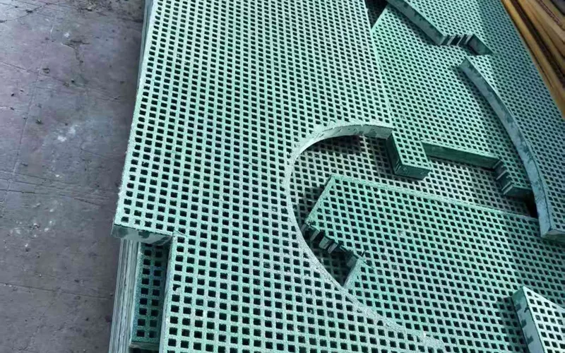
If two pieces have the same outer dimensions but different openings or support roles, they are not interchangeable. The packing and installation labels should carry the same IDs as the drawing. This reduces the chance that a removable service piece is installed in a fixed position or a panel is flipped so that its top face or bar direction is wrong.

What Strong Riser Systems Add
GRP Safety’s service riser grating page presents grating and supports as a coordinated system. Riser Grating’s panel specification page usefully compares mesh, panel thickness and removable systems. Dura Composites’ riser-void page raises floor level, supports, future services and installation stage, while Waux’s installation guide separates cast-in, rebated and retrofit support conditions.
The common strength is system thinking. The common gap is that a buyer can still receive a panel quotation without a clean service schedule or a removability plan. Our factory contribution is to make those interfaces explicit:
- the opening is measured from the service and access envelope;
- the support and interrupted bars are shown on the same drawing;
- fixed and removable pieces have different IDs and fixing requirements; and
- the cut-edge, fabrication and inspection scope follow the piece through packing.
This is not a claim that a more complicated panel is always better. A simple fixed floor with one planned future service bay can be the right answer. The goal is a layout that the operator can maintain, not the maximum number of cutouts.
The Enquiry Review We Can Perform
We can review the shaft boundary, panel layout, service schedule, piece geometry, edge treatment, agreed support drawing, fixings and packing identity. We can flag missing clearance, a cutout that crosses an unclear support, an unmarked removable piece or a requested panel size that cannot be handled from the access shown.
We do not approve the fire strategy, smoke or water sealing, electrical safety, structural design, fall protection, lifting plan or installation sequence unless that responsibility is included in a written scope. A clear boundary lets the project engineer approve the shaft system while the factory delivers fabricated pieces that match the coordinated drawing.
Coordination sequence
From Shaft Services to Identified Riser Pieces
Seven steps connect the service plan to cutting, access and installation.
Fix the shaft wall, floor level, columns and measurement grid before positioning any service.
Include flanges, insulation, trays, valve operators, tools and the movement needed for maintenance.
Choose panel joints and bar directions that preserve walking routes, bearing and manageable removable pieces.
Mark every opening edge and the added frame, trim, bearer or transfer member required around it.
Give each piece an access class, ID, mass, lift direction, restraint and reinstatement position.
Show connections to walls, stairs, guardrails, fire stopping, cable trays and any shaft sealing system.
Keep the approved revision through cutting, edge treatment, marking, packing and installation checks.
Boundary checks
Five Responsibilities a Grating Cutout Does Not Satisfy
Product geometry and project safety need to remain visibly different.
- A grating cutout is not a structural opening frame — Cutting the panel creates an opening. It does not create the added support needed to carry the remaining walkway or the new free edge.
- Edge sealing does not restore severed bars — Sealing protects the cut laminate. The structural consequence of removing bars remains and requires its own support decision.
- A grating floor is not a fire or smoke seal — Open grating passes air and smoke. Where the shaft requires a tested fire, smoke, acoustic or water boundary, that system must be designed and evidenced separately.
- Nonconductive does not replace electrical safety design — FRP may be useful around electrical services, but clearances, isolation, bonding, arc and equipment requirements remain the responsibility of the electrical design.
- A removable piece is not just an unfastened panel — It needs a size and mass that can be handled, defined lift points, restrained refitting, identification and a plan for temporary exposure while open.
Project checklist
What to Send With a GRP Riser Cutout Enquiry
Ten items let the factory review the actual service and panel layout.
- Shaft plan and sections — Wall dimensions, floor level, columns, openings and surrounding structure.
- Service schedule — Pipe, duct, tray and equipment IDs with size, flange, insulation and future capacity.
- Maintenance action — Valve operation, inspection, lift path, tool space and frequency.
- Common datum — Coordinates and drawing revision for every service and panel joint.
- Support layout — Perimeter and intermediate supports, bearing width, bar direction and added frames.
- Installation method — Cast-in, formed rebate, top-fixed frame, retrofit support or prefabricated module.
- Construction stage — When the floor is installed, what covers the void before it, and how follow-on trades are controlled.
- Opening schedule — Each cutout shape, size, location, clearance and interrupted bar.
- Access pieces — Fixed, lift-out, hinged or cover; mass, lift points, gaps and reinstatement.
- Environment — Moisture, temperature, chemical, electrical, fire and cleaning exposure.
- Interfaces — Guardrails, stairs, fire stop, cable tray, pipe supports and any shaft sealing system.
- Evidence — Required load, material, fire, inspection and conformity documents.
Piece schedule
GRP Riser Grating Fields That Must Match
The panel, opening, support, access and evidence should describe the same delivered set.
Request a Project Quote| Specification | Value |
|---|---|
| Grating format | Molded, mini mesh, covered or pultruded Select by span, mesh opening, walking duty, handling and service arrangement. |
| Opening input | Service envelope Include flange, insulation, tools, movement and future services; do not use pipe OD alone. |
| Panel layout | Fixed and removable piece schedule Give every piece an ID, access class, size, direction and edge condition. |
| Support | Project-specific frame and bearing Show perimeter supports, intermediate members and any added support around openings. |
| Cut edge | Agreed treatment State whether factory or site cut, sealer and inspection requirement. |
| Surface | Standard, concave, grit or covered Match walking condition, dropped objects, cleaning and barefoot or boot use. |
| Environment | Moisture and other exposure Resin and hardware are reviewed against the actual shaft environment. |
| Supply boundary | Written scope Frames, brackets, anchors, shaft boundary systems and installation are confirmed per project. |
Request a review
Send the Riser Services and Support Drawing
Use one datum for pipes, ducts, panel joints and maintenance access.
- Show every service envelope
- Mark support around every opening
- Give removable pieces a lift and refit plan
GRP Riser Grating Cutout Questions
How large should a riser grating cutout be?
Is one pipe diameter enough for the drawing?
Why put services and grating on the same drawing?
Does every opening need a frame?
Can cut edges be sealed and left unsupported?
Can part of the riser grating be removable?
What happens while a panel is open?
Does GRP riser grating provide fire stopping?
Can the factory approve the riser shaft structure?
This content was prepared and reviewed by Dengtai Industry’s technical and production team using the project conditions, available product data and applicable documents. Limits that require design, testing or approval are identified in the content. Content last checked: