Application
GRP Riser Grating for Building Service Shafts
A riser shaft has pipes and cables passing through it, people who need to reach them, and a limited amount of space to do both. The panel, the openings and the support around them are designed on one drawing, not solved on site.
Drawing inputs
What a Riser Shaft Drawing Has to Show
Six items, and the first two decide most of the panel layout.
| What the drawing has to give | How it is stated | Why it decides the panel |
|---|---|---|
| Shaft opening and floor level | Shaft boundary dimensions, floor level and the surrounding structure | Sets the panel outline, the number of pieces and how they are carried at the edges |
| Each pipe, duct or cable route | Outside diameter or envelope, coordinates on a stated grid, and the drawing revision | Decides where openings fall, which bars are cut and how much structure remains |
| Allowance for movement and future service | Whether openings need clearance for expansion, alignment tolerance or a later cable | A design decision belonging to the services engineer, not a factory default |
| Access requirement | Which areas are walked on, how often, and what tools are carried | Sets the load case and the surface requirement |
| Removable areas | Which pieces lift, in which direction, and how they are identified | Sets piece sizes, weights and the fixing arrangement |
| Support and framing | Edge support, intermediate supports and bearing widths | Decides the clear span and where the openings can sit relative to supports |
Process
From Shaft Drawing to Delivered Riser Grating
Six steps that keep the services, the openings and the panel layout in step.
Panel pieces, openings and supports in the same coordinate system and revision, so a pipe that moves is visible against the panel layout.
An opening interrupts bars, so the remaining structure and the support around it are reviewed for each one rather than assumed from the opening size.
Sizes that can be handled, identification on each piece, and whether fixings can be released with the tools the maintenance team carries.
Resin direction from the environment, surface from the walking condition, and clips from the panel height and the support.
Cut list, openings, edge sealing and packing identification, matched to the approved drawing revision.
Piece numbers, support bearing, opening clearances and whether removable pieces are refitted with their original fixings.
Boundaries
Three Boundaries on Riser Grating Supply
The points where an assumption becomes a site problem.
- System supply is not confirmed by a panel quotation — We supply grating, cut pieces, fixings and edge sealing. Whether a complete riser system — frames, brackets, anchors and installation design — is part of the supply is confirmed per project and stated in writing.
- Opening size alone does not decide the detail — A 300 mm pipe and a 300 mm opening are not the same requirement. What matters is the position of the opening relative to the supports, which bars it interrupts and how the remaining structure transfers load around it.
- Sealing does not restore cut bars — Sealing a cut edge protects the laminate. It does not rebuild a bar that was severed, and it does not remove the need to support the opening.
Project inputs
What to Send for a Riser Grating Review
Six items, mostly from one coordinated drawing.
- Shaft drawing — Shaft dimensions, floor level, surrounding structure and the drawing revision.
- Service layout — Each pipe, duct or cable with size and position, and any allowance for movement or future services.
- Access and load — Who walks on the grating, how often, what is carried, and the clear span between supports.
- Removable pieces — Which areas lift, and the maximum piece weight that can be handled in the shaft.
- Environment and requirements — Moisture, temperature, any chemical contact, and any electrical or fire requirement in the shaft.
- Supply scope — Whether the project needs panels only, or panels, fixings, edge sealing and a defined installation design.
Request a quote
Send the Shaft and Services Layout
Openings, supports and removable areas belong on the same drawing.
- Molded and pultruded grating produced in house
- Full panels or factory cut-to-size pieces
- No fixed minimum order quantity
Riser Grating Questions
Do you supply the support frame for a riser shaft?
How are openings around pipes handled?
Can part of the grating be removable for maintenance?
Does the grating need sealing against water or fumes?
Continue With Riser Grating
Applications directory
The other applications we can describe from our own supply experience.
Cutting and sealing
Openings, cut lists, factory cutting and edge sealing.
Installation planning
Support, fixing and opening checks before delivery.
Clips and fixings
Clip families, and how each one is matched to the panel and support.
Technical resources
The technical material behind this application.
FRP grating offshore details
Vinyl ester or phenolic directions, with fire and corrosion treated as separate requirements.
Fiberglass dock grating details
Barefoot, permanently wet walkways where grip, drainage and chlorine or salt exposure are decided together.
Why Riser Shafts Need a Coordinated Drawing
A riser shaft is where several disciplines meet in a small space. The services engineer knows where the pipes are, the structural engineer knows where the supports can go, and the maintenance team knows which valves need reaching. The grating panel sits between all three, and it is the one component that has to accommodate every opening at once.
That is why the working document is a single coordinated drawing: shaft boundary, panel pieces, each service with its position, supports, and the areas that have to lift. When those are on one sheet, an opening that lands directly over a support or a pipe that has moved 50 mm since the last revision becomes visible before the panels are cut. When they are on separate sheets, it usually becomes visible in the shaft.
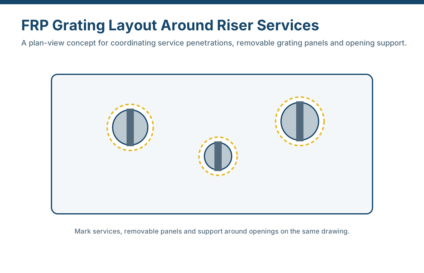
Openings, Support and Removable Pieces
An opening changes the structure around it. Cutting through bars interrupts the load path, and how much that matters depends on the position of the opening, the number of bars involved and the distance to the nearest support. An opening in the corner of a panel supported on all four edges behaves differently from the same opening in the middle of a span. Adding support around the opening is normal practice; sealing the cut edge is a separate measure that protects the laminate.
Removable pieces need the same discipline as the panels themselves. Inside a shaft the available handling space is often poor: a piece may have to be lifted vertically with limited headroom, and it may be difficult to see which panel came from where. Sizes that one person can manage, pieces that are numbered on the drawing and a fixing arrangement that can be repeated without measurement are what make a riser installation workable over its life.
Materials, Fixings and What Stays With the Project
The resin direction follows the environment inside the shaft — usually moisture and temperature rather than chemical exposure, though plant rooms vary. The walking surface follows the access condition. Fixings are matched to the panel height, bar width and the support section, with galvanized or stainless steel chosen for the regime.
The project boundary is worth stating clearly. We supply panels, cut pieces, fixings and edge sealing, and we review the configuration against the drawing. The structural design of the shaft, the support steelwork, fire stopping and any electrical or smoke requirement in the shaft remain the responsible engineer’s scope unless a wider supply is agreed in writing for the specific project.
Content last checked: