FRP grating obstruction details
FRP Grating Around Pipes and Columns: Cutouts and Trim
A pipe and a structural column are not the same obstruction. Measure the real envelope, position the opening from a common datum, identify interrupted bars and assign structural trim, edge treatment and clearance separately.
Prepared by
Dengtai Industry
Published
·
Reviewed

A process access reference. Local pipe and column details must be coordinated with the floor layout. Photo: Dengtai Industry.
FRP grating around a pipe is not automatically the same detail as FRP grating around a column. A pipe is a service that may carry a flange, insulation, movement, a valve and removal requirements. A column is part of the structural system and has its own base, loads and connection. The grating opening provides clearance in both cases, but the engineering and maintenance questions are different.
This page covers local openings in industrial FRP floor grating, access platforms and service risers. It does not provide a universal pipe clearance or a hole-size rule. It shows the information needed to review each obstruction against the panel grid, support layout, walking route and trim responsibilities.

Measure the Obstruction, Not Just the Visible Pipe
The visible pipe body is often the smallest part of the requirement. Record flanges, insulation, valve operators, cable trays, clamp bands, electrical clearances and the tools needed to work on the service. For an insulated pipe, the outside insulation may govern the opening. A valve may require a hand and tool approach beyond the pipe envelope.
For a structural column, record the column or base-plate envelope and its connection into the structure. The grating should provide the required clearance without becoming the column anchorage. If the obstruction is a cluster of pipes and supports, dimension the whole cluster on one common datum rather than treating each circle independently.
Keep the local service cutout separate from the repeating mesh opening. A cutout may be a single large ring or notch, while the panel mesh controls dropped objects, drainage and cleaning elsewhere on the walking surface. For service shafts with people or equipment below, compare standard mesh, mini-mesh and solid-top with the actual object and ventilation requirements. Use the mini-mesh guide and dropped-object comparison rather than describing both openings as one size.
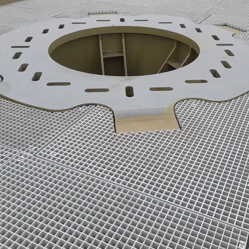
Identify the Bars and Walking Area the Cut Removes
The opening interrupts a grid or directional bearing system. Record the panel type, bar direction, the members removed and the remaining strip to the panel edge, joint or support. A cut near a support may affect the local load path differently from one in the middle of a field. A clustered opening may leave narrow strips that are difficult to support or inspect.
For molded grating, the integral grid provides a repeating load path but not every possible opening is automatically acceptable. For pultruded grating, the bearing-bar direction and span are especially sensitive to piece rotation. The molded cutout guide and load and span guidance explain the review inputs.
Opening geometry does not prove the finished load path. Record the walking duty, point or wheel load, tool and equipment load, temporary construction load, remaining span, bearing and deflection limit. A standard load table may describe a different panel and support configuration from the cut piece. High-Mat’s cutout guidance explicitly warns that a cutout can move the layout outside the original table assumptions. The finished local condition requires project-specific review.
Separate Installation, Movement and Maintenance Clearance
Clearance can serve several purposes. Installation clearance lets the panel pass the service. Service movement clearance allows expansion, vibration or alignment change. Maintenance clearance provides hand and tool room. Inspection clearance lets the owner see the pipe and cut edge. State which one drives the dimension instead of allowing a generic gap to serve all three.
Where the service requires a precise electrical clearance, fire separation, insulation gap or water path, those requirements come from the relevant project discipline. The grating cutout is not proof that the surrounding system meets them.
Fire and service boundaries need particular care. A pipe opening can pass through a floor that also forms part of a smoke, fire, acoustic or water strategy. A close-fitting cutout is not a fire-stop seal. Coordinate the opening clearance, fire-stopping product, pipe sleeve, electrical separation and inspection route as separate interfaces. The fire-rating guide and anti-static guide provide the relevant product-evidence direction where those duties apply.
Separate Edge Seal, Finish Collar and Structural Trimmer
A cut edge should receive the specified treatment to protect the exposed composite. That treatment does not restore a bar or carry load. A finish collar or penetration trim may cover the gap, control debris or improve appearance. It is still not a structural member unless it has been designed and connected as one.
Where the local load path needs support, a trimmer, bearer or frame must connect to an adequate support. The cutting and sealing guide covers fabrication practice. The support design, anchors and connection to the surrounding frame remain a named project responsibility.
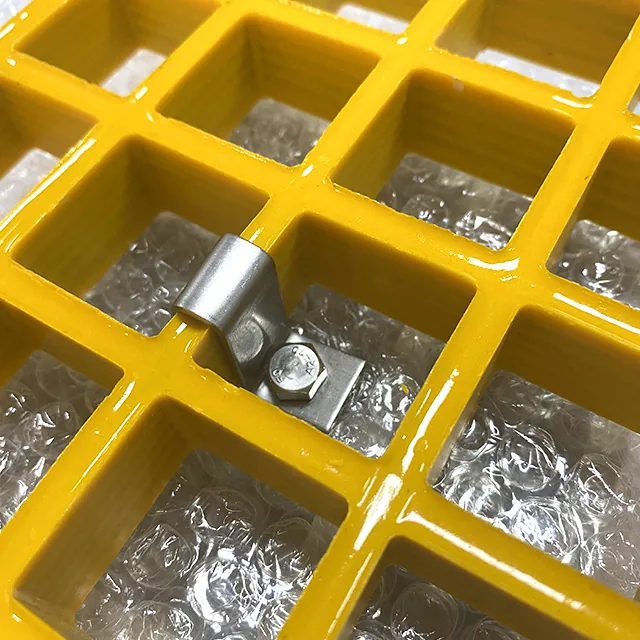
Fibergrate’s engineering guidelines also separate hold-down restraint from support around a cutout. The project should identify whether a trimmer, added frame or supported edge is required; a finish collar, sealer or standard panel clip cannot be counted as structural support without a designed function.
QY Metal Tech’s cutout and edge-trim RFQ guide reinforces that the opening, notch, edge trim, panel mark and support span must be stated separately before a quote or cut is agreed. A finish collar should not be written into the drawing as an assumed structural trimmer.

Keep the Pipe and Column Interfaces Independent
A process pipe should not brace the grating unless that composite interface has been intentionally designed. Pipes can expand, vibrate, settle or be removed for maintenance. Using the pipe as a prop can damage both systems and make future work unpredictable.
The cutout review above applies the same rule: keep the process pipe structurally separate unless the design intentionally makes it part of the support system. Allow for equipment movement, inspection and removal, not only pedestrian load.
A structural column may carry loads much greater than the panel, but the grating still needs a separate clearance and support condition around it. The guardrail post opening guide shows the same principle for a different structural member: the post or column is not anchored by the grating clip.
Measure the Finished Cut and Record Changes
The approved drawing is not proof that the installed cut matches. Measure the finished opening, remaining strips and service clearances after fabrication or field modification. Record any approved change and connect it to the original piece ID. If the as-built result changes the bars, support or access route, the review has to reopen.
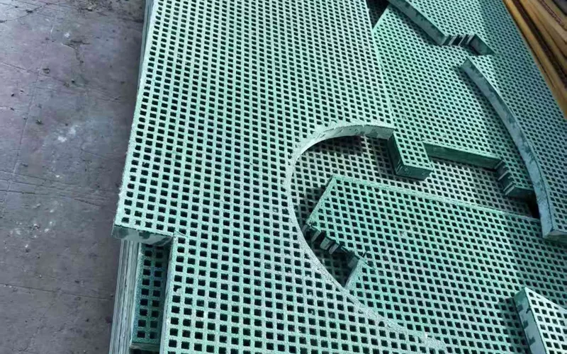
Our Factory View: Cut the Record, Not the Photograph
We can cut the panel outline, opening and agreed edge treatment from a dimensioned piece schedule. We can mark and pack the finished pieces so the installer can match them to the drawing. We can also flag where the obstruction envelope, interrupted bars or support ownership are incomplete.
We do not set the structural clearance, approve the pipe movement or design the host frame from a photograph. The useful factory input is a dimensioned obstruction schedule, panel layout and support drawing on one revision. A precise cut with an unrecorded structural assumption is not a finished engineering detail.
Drawing vocabulary
Pipe and Column Cutout Terms
- Obstruction envelope
- The complete occupied or moving space of a pipe, flange, valve, duct, tray or column, including insulation, base plates and maintenance tools where relevant.
- Pipe clearance
- The gap between the service envelope and the cut edge. It can support installation, movement, inspection, thermal change and maintenance access.
- Column opening
- A clearance or notch in the grating around a structural column or post. The opening accommodates the column but does not become its structural support.
- Interrupted bar
- A structural or grid member removed by the cut. Its position, remaining strip and relation to supports require review.
- Structural trimmer
- A designed frame, bearer or edge member that restores or creates a load path around an opening where the project requires it.
- Edge seal
- A protective treatment applied to the cut composite edge. It does not replace a bar, provide bearing or transfer structural load.
- Collar or penetration trim
- A finish, weather or debris detail around a service. Its architectural role must not be confused with structural support of the grating.
- As-built opening
- The measured final shape and location after cutting, including any approved field change. A drawing dimension is not proof of the field result.
Release check
When a Local Opening Is Ready for Fabrication
Specify this if…
- The real pipe, equipment or column envelope is measured and positioned.
- The opening shape, corners and clearance are dimensioned from a common datum.
- Panel type, bar direction and the interrupted bars are shown.
- The remaining strip and distance to supports are visible.
- Any structural trimmer, frame or bearer has a designer and connection.
- Edge sealing, finish trim and inspection are separately specified.
Look elsewhere if…
- The opening follows the pipe OD while ignoring flange or insulation.
- A column is treated as the same kind of obstruction as a moving service.
- The drawing relies on a clip to support an opening edge.
- The pipe is expected to prop or stabilize the grating.
- The remaining strip is too narrow or unsupported but has not been reviewed.
- A finish collar is described as a structural trimmer.
Geometry comparison
Round Pipe, Square Column and Clustered Obstructions
| Obstruction | Main geometry question | Required project input |
|---|---|---|
| Round pipe | Pipe body, flange, insulation, sleeve and maintenance tool envelope | Centre coordinates, OD, clearance, movement and service access |
| Insulated pipe or valve | The route to operate, inspect or remove the fitting | Installed and maintenance envelopes, hand and tool space |
| Rectangular duct or tray | Opening axes, corners, cable allowance and service support | Width, depth, corner treatment and future capacity |
| Structural column | Column or base-plate envelope and connection into the structure | Column coordinates, base envelope, clearance and independent support design |
| Clustered obstructions | Combined loss of grid, narrow strips and maintenance route | One coordinate schedule for the whole cluster and interrupted members |
| Access opening beside obstruction | Both the through-service clearance and the person's reach or removal route | Opening shape, lift direction, temporary cover and open-state control |
Cutout record
Fields for a Pipe and Column Cutout Schedule
| Schedule field | What to record | Why it matters |
|---|---|---|
| Obstruction ID | Pipe, duct, valve, column or base plate identifier | Connects the cutout to the actual object |
| Obstruction envelope | OD or outer dimensions, flange, insulation and movement | Defines the real clearance requirement |
| Datum position | X and Y coordinates from a named grid or edge | Prevents a shape that looks right but sits in the wrong place |
| Cutout geometry | Circle, rectangle, notch or combined shape with corner radius | Determines which bars and edges are interrupted |
| Panel and bar direction | Piece ID, construction and directional members | Shows whether the cut interrupts a main load path |
| Remaining strip | Width to edge, joint and support after cutting | Reveals narrow, unsupported or hard-to-inspect conditions |
| Structural trim | Required frame, trimmer or bearer and design reference | Separates support from finish |
| Edge treatment | Seal, coating and inspection requirement | Protects the cut composite without claiming structural capacity |
| Service interaction | Pipe movement, vibration, temperature and equipment removal | Prevents accidental bracing or future damage |
| As-built result | Final measured outline, support and photos or inspection record | Closes the difference between drawing and installation |
Seven-step review
From Site Obstruction to Finished Grating Piece
Separate a pipe or duct from a structural column and record its actual ID.
Include flange, insulation, base plate, movement and required tool space.
Position the obstruction and panel opening from the same plan reference.
Show shape, corners, clearance and whether the opening meets a panel edge.
Record the panel construction, bar direction, removed members and remaining strip.
Identify any required frame or bearer and the responsible designer.
Keep the piece ID through cutting, edge treatment, installation and as-built measurement.
Before cutting
FRP Grating Pipe and Column Cutout Checklist
- Obstruction identified — The pipe, duct, column or base has its own ID and type.
- Full envelope measured — Flanges, insulation, movement and maintenance tools are included.
- Common datum shown — The opening and services use the same coordinates.
- Cut shape dimensioned — Width, depth, diameter, corners and clearances are complete.
- Panel type recorded — Product family, thickness and bearing direction are known.
- Interrupted bars marked — Removed members and remaining strips are visible.
- Structural trim defined — Any required trimmer, bearer or frame has its own design.
- Pipe independence checked — The service is not an accidental load path for the grating.
- Column support separated — The grating opening does not define the column base connection.
- As-built evidence specified — Final opening and support can be measured and inspected.
Scope boundary
What Local Trim Does Not Fix

Edge sealing is not a trimmer
Sealing protects the composite. It does not restore a removed bar or provide bearing.
A pipe is not a support
Process services can move, vibrate or be removed. They should not become accidental props.
A collar is not a structural frame
A finish or penetration collar can control debris or appearance without carrying the grating.
A column opening is not a base connection
The column must reach its designed support; the grating only provides clearance around it.
Cutout review
Send the Obstruction Plan and Grating Layout
- Molded and pultruded grating produced in house
- Full panels or factory cut-to-size pieces
- No fixed minimum order quantity
FRP Grating Pipe and Column Questions
How much clearance should FRP grating have around a pipe?
Is a square column opening the same as a round pipe cutout?
Can the pipe support the cut edge of the grating?
Does a trim around the opening restore structural capacity?
What should the cutout drawing show?
Can the opening be made on site?
What if the finished opening differs from the drawing?
This content was prepared and reviewed by Dengtai Industry’s technical and production team using the project conditions, available product data and applicable documents. Limits that require design, testing or approval are identified in the content. Content last checked: