Static-control system review
Anti-Static FRP Grating: Defining Panel, Connections and Testing
Anti-static is not just a colour or a resin additive. Define the required electrical result, trace the path through panel joints and supports, connect it to the named earth, and state how the installed system will be measured and maintained.
Prepared by
Dengtai Industry
Published
·
Reviewed

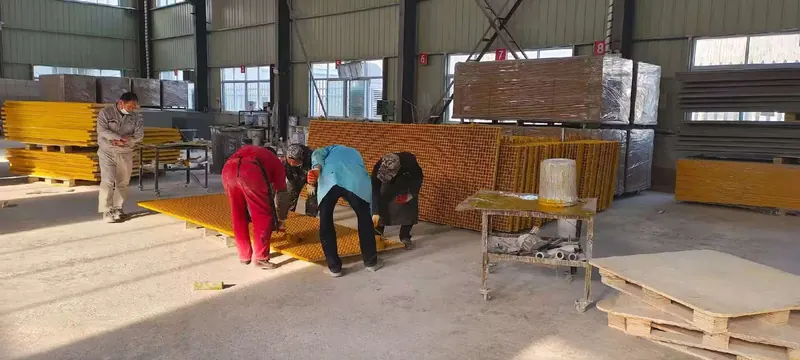
The grating is part of an electrical path only when the installed connections and earth route are defined. Photo: Dengtai Industry.
Electrical vocabulary
Anti-Static, Dissipative and Conductive Are Not Interchangeable
Define the property and measurement path before asking which panel is “anti-static.”
- Electrically insulating FRP
- Standard FRP grating is normally an electrical insulator. Insulation can be desirable around live equipment, but it does not provide electrostatic dissipation.
- Anti-static
- A general market term for a material or system intended to reduce static charge. It is not a complete specification unless the project adds a method, resistance range and measurement path.
- Static-dissipative
- A project- or standard-defined electrical classification. Do not apply a resistance band from one manufacturer or product to another without checking the governing document.
- Conductive
- A material or surface with a much lower electrical resistance than ordinary FRP. “Conductive,” “anti-static” and “dissipative” are not interchangeable without the project's definitions.
- Surface resistance
- A measurement across a defined surface using stated electrodes, voltage and conditioning. It is different from volume resistance and from resistance to an earth point.
- Resistance to ground
- The electrical path measured between the floor or panel and the specified earth connection. It depends on surface condition, fixing, supports and the earth detail.
- Earthing or grounding point
- The named electrical connection used to discharge the system. The installer, conductor, fixing, accessibility and inspection responsibility belong to the project.
- Conductive path
- The continuous route from the walking surface through the panel, joints, clips or bonding details and supports to the named earth point.
- Installed-system test
- A test performed after installation with the agreed instrument and path. A panel sample result does not automatically describe every joint, cutout or repair.
When to use this review
When an Anti-Static Grating Request Needs a System Review
A grounded floor is a chain of panel, connection, earth and verification rather than one material label.
Specify this if…
- The project states a static-control, ESD, dissipative or conductive requirement.
- The area contains sensitive electronics, flammable powders, solvents or another identified static hazard.
- The floor has panel joints, cutouts or supports that interrupt a simple panel path.
- The project requires a test to earth after installation.
- Cleaning, wear or repair can affect the conductive surface.
Look elsewhere if…
- The requirement says only “anti-static” with no method, target or responsible standard.
- A black panel is being treated as proof of conductivity.
- Only a panel resistance result is available, with no installed path or earth detail.
- Clips, supports and sealants are being selected without checking whether they interrupt the path.
Claims and proof
What an Anti-Static Grating Claim Must Prove
The same wording can hide different electrical properties, specimen paths and installation assumptions.
| Phrase or assumption | What it may cover | What still has to be proved |
|---|---|---|
| “Anti-static grating” | A general product direction for controlling charge | The applicable definition, resistance range, test method and installed path |
| “Black conductive surface” | A possible visual description of one conductive construction | Continuity through edges, joints, fasteners, supports and repair areas |
| “Less than [resistance value]” | A result for the stated specimen, electrodes, voltage and condition | The same result for the full installed system or another product |
| “Grounded grating” | An intended connection to an earth point | The conductor, fixing method, earth identity, installation inspection and owner |
| “Maintenance-free” | A marketing term unless a defined inspection regime is supplied | Cleaning effects, surface wear, continuity and repeat-test responsibility |
System fields
Anti-Static FRP Grating RFQ and Drawing Fields
The information needed to connect the electrical requirement to the delivered and installed system.
| System item | Information required | Why it matters |
|---|---|---|
| Electrical target | Standard or project clause, resistance range, test method and measurement path | The same number can describe different electrical properties |
| Panel construction | Molded or pultruded, conductive matrix or surface layer, colour, thickness and cutouts | Conductivity can be throughout the product or concentrated at a surface |
| Joints | Panel gap, edge treatment, joining strip, conductive clip or bonding detail | An insulating gap or trim can separate otherwise conductive panels |
| Supports and fixings | Clip material, coating, support contact and bonding connection | A conductive panel does not automatically make the support path conductive |
| Earth detail | Earth point, conductor, fixing, protection and responsible party | The electrical route is incomplete until its destination and installer are named |
| Verification | Sample test, installed test, instrument, conditioning, date and acceptance value | Production and installation need evidence at their own level |
| Maintenance | Cleaning products, wear, repairs, continuity checks and records | Residue or a new coating can change the surface path |
Review sequence
How to Define an Anti-Static Grating System
Six steps from the project requirement to a verifiable installed path.
Obtain the exact standard, edition, area classification or client specification and the resistance property it asks for.
Draw the route from walking surface through panel, joints, bonding points and supports to the named earth.
Confirm whether conductivity comes from the matrix, a dedicated surface or another construction, and how edges and cutouts are treated.
Check conductive clips or straps, insulating coatings, support continuity, perimeter contact and access to the earth point.
Separate the panel sample test from the installed-system test and state the instrument, method, conditioning and acceptance value.
Record who cleans, repairs and re-tests the path, and which change triggers another verification.
Anti-Static FRP Grating Is a System, Not a Colour
An anti-static grating project is complete only when the charge has a defined path from the walking surface to an identified earth point. The panel matters, but so do the joints between panels, the clips or bonding details, the supports, cut edges, repairs and the final measurement. A supplier who quotes only a black panel has answered one part of the question.
Start with the property the project needs. “Anti-static,” “static-dissipative” and “conductive” can be defined differently in different standards and client specifications. A test may measure surface resistance, volume resistance or resistance to ground. Those are different paths, not alternative names for a single number.
This guide is a Dengtai Industry procurement and engineering checklist for our grating configurations. The factory can review the grating construction and the information available for the proposed order. The electrical classification, selected earth point, installation work and final project approval remain with the responsible electrical or safety authority.

First Define the Electrical Target
Do not start with a product adjective. Start with the clause or client requirement. A useful enquiry identifies:
- whether the project asks for anti-static, dissipative or conductive performance;
- the standard, edition or client procedure that defines the category;
- the exact property to be measured;
- the resistance limits and units;
- the test voltage, electrodes and conditioning;
- whether the result is required on a sample, delivered panel or installed floor; and
- which authority will accept the evidence.
If the project names only “anti-static,” send the surrounding specification or ask the electrical authority to clarify. Two suppliers may quote the same phrase while describing different surface treatments, test paths and acceptance values.
Conductive Matrix, Conductive Surface or Ordinary FRP
FRP is normally electrically insulating. A static-control format therefore needs a deliberate conductive route. The route may be designed through the resin matrix, through a dedicated surface layer or through another confirmed construction. These are not visually interchangeable:
- A conductive matrix distributes the intended filler through the panel material, but the exposed surface and cut edges still need confirmation.
- A conductive top layer can provide a controlled walking surface, but wear, cleaning and edge continuity become central to the installed path.
- An ordinary black panel may contain only pigment. Carbon or graphite may produce a dark appearance, but a dark appearance does not prove that carbon is present or that the resistance target is met.
- A conductive coating is a separate layer with its own thickness, adhesion, repair and compatibility requirements.
Ask for the actual construction and the document that covers it. A photograph of a black panel is not a material specification.
A Conductive Format Can Change Other Evidence
The conductive route can change more than electrical resistance alone. A filler dispersed through the resin, a dedicated conductive surface or a conductive coating may alter the formulation, exposed surface, mass or process behaviour. It may also affect the chemical, fire, UV and structural evidence needed for the finished panel.
That does not mean every conductive product performs worse in every property. It means the ordinary FRP report cannot be carried across automatically. Match each claim to the conductive construction, resin system, surface, batch and specimen actually supplied.
| Change in the construction | Evidence to re-check | Order action |
|---|---|---|
| Conductive filler or resin batch | Chemical resistance, fire performance, UV behaviour, mass and structural data | Identify the grade and confirm which reports or inspections apply |
| Conductive top layer or coating | Wear, adhesion, cleaning, repair and edge continuity | Define the protected area and the maintenance method |
| Pigment or colour | Appearance approval and, for outdoor service, UV and weathering evidence | Approve a physical sample and keep colour separate from the electrical result |
| Cutouts, cut edges or repairs | Continuity, edge condition and repair compatibility | Show the modification on the drawing and name the re-test or inspection |
Many conductive constructions are supplied in black or another dark colour because the conductive formulation and appearance are linked. Other colours may be technically possible, but availability and appearance approval depend on the confirmed construction. We treat the electrical format, colour sample and performance evidence as one order decision, not as three independent catalogue choices.

Joints, Clips and Supports Can Break the Path
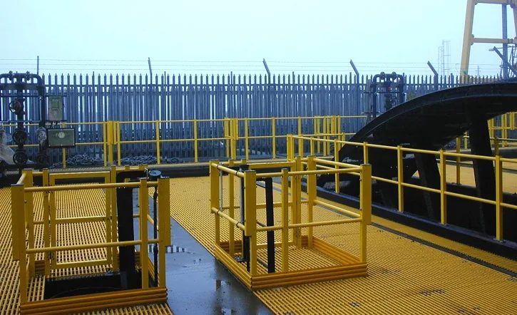
The resistance of one panel does not describe a floor made from several panels. Charge has to cross panel-to-panel joints and reach the earth connection through the components actually installed.
Review these details together:
- whether the panel-to-panel gap is bridged by a conductive joining detail;
- whether clips, bolts, washers or bonding straps are conductive and remain in contact;
- whether a coated support, gasket, levelling pad or edge trim introduces an insulating layer;
- which perimeter or earth connection point is accessible after installation;
- how a removable panel is reconnected after maintenance; and
- whether the installer can demonstrate continuity along the intended route.
Our supply scope may include the grating and specified accessories, but the project drawing must still identify the electrical path and the party responsible for each connection. A “grounded” note on a drawing without conductor, fixing and earth-point details is not a completed electrical design.
Where the conductive route serves a process platform, use the chemical platform grating review to coordinate the electrical path with chemical zones, maintenance openings, supports and the supply boundary.
Test the Property the Project Names
Electrical test methods are sensitive to the specimen, electrodes, voltage, humidity, temperature and surface condition. Agree the method before production and do not convert one result into another.
A surface-resistance result does not automatically prove resistance to ground. A resistance-to-ground result for a test assembly does not automatically apply to every panel joint or cutout. The test may also need a specified conditioning period, cleaning state and contact pressure. These details belong in the acceptance record.
Where a project uses a standard such as an IEC static-control method or a client procedure, use the exact edition and method requested. The publisher’s scope and the purchasing specification govern the test. Do not accept a manufacturer’s statement that a product is “antistatic” without knowing whether the number refers to surface resistance, volume resistance, leakage resistance or a complete grounded assembly.
Cut Edges, Repairs and Cleaning
Cuts and holes are especially important for a surface-conductive panel. They can create an untreated edge, interrupt a surface layer or change the distance to the earth point. Where continuity depends on the surface, the order drawing should show cut locations and the repair method used at exposed edges.
Repairs present the same problem. An ordinary resin patch can restore appearance while masking the conductive path. The repair material, application method and re-test requirement have to suit the actual construction. Cleaning is also part of the system: a film of oil, release agent or some floor treatments may change the measured surface condition. If the project defines a post-cleaning test, state the cleaning product and drying or conditioning condition.
Where Anti-Static Systems Commonly Lose Continuity
The most frequent problem is not a missing conductive panel; it is an unrecorded break between items that were each described as conductive. Review these points before releasing the order:
- Black is accepted as conductive. A dark pigment can look correct without the specified conductive construction. Require a resistance property and test record, not a colour description.
- The panel is tested but the installation is not. Panel-to-panel gaps, insulating clips and isolated supports can leave each panel conductive while the floor as a whole has no reliable path to earth.
- The wrong resistance property is compared. A surface-resistance value and a resistance-to-ground value cannot be placed in one column and treated as equivalent.
- Ordinary accessories are used. A standard polymer gasket, levelling pad or coated clip may interrupt contact. The assembly drawing must show the intended conductive path and any intentional insulation.
- Cleaning or maintenance changes the surface. A film can raise the measured resistance, while an abrasive cleaner or unsuitable coating may damage the conductive layer. The maintenance procedure has to preserve the intended surface.
- Cutouts and repairs are omitted from the drawing. The tested panel size is not necessarily the delivered piece with an opening, edge seal or local repair.
- The test evidence has no scope. A report without specimen, electrodes, voltage, conditioning and result cannot be matched to the requirement.
Our factory review therefore starts with the proposed construction and the drawing interfaces. If the documents show only a panel colour and a vague instruction to “earth,” we return the list of items that must be resolved before the offer can be treated as a system.
Panel Test Versus Installed-System Test
Both levels of evidence can be useful, but they answer different questions.
| Evidence level | What it can show | What remains open |
|---|---|---|
| Panel sample test | A result for the named sample, surface, electrodes and test conditions | Joints, supports, earth path and installation quality |
| Production-piece check | The agreed property on the identified finished panel | Connections made on site and system continuity |
| Installed-system test | The measured route after assembly, at the stated locations and conditions | Long-term wear, cleaning effects and future maintenance |
| Maintenance re-check | Whether the agreed path still passes at a later date | A universal service life or immunity to damage |
Ask for the report or record that matches the level at which the requirement is written. If the project requires an installed test, the installer, instrument, calibration, test points and acceptance form should be agreed before work starts.
A useful test report should identify the laboratory or testing party, date, specimen, product construction, conductive format, method and result. It should state the conditioning before the measurement and whether the test was performed on a new, cleaned, worn or repaired surface. If the report contains an acceptance range, the project should confirm that the same range and property apply to the specified area and installation.
Do not compare a panel resistance result from one supplier with a resistance-to-ground result from another and conclude that one system is better. Establish the same test first, then compare the numbers. Where the project has no test requirement, record that the system was selected from the construction and sample without claiming a measured electrical class.
Quality Records and Scope
The quality and documentation guide explains the difference between a sample report, an order certificate and a dimensional record. For an anti-static order, keep these linked to:
- the exact grating construction and conductive format;
- the resin, colour and surface;
- the approved drawing and cut list;
- the panel-level test or inspection;
- the installation connections and earth points; and
- the final acceptance record.
If the available document was produced on a different specimen or test path, identify the gap. Do not rewrite a historical sample report as a new installed-system approval.
Our Factory Review Boundary
We can review the anti-static format together with the panel structure, surface and available project information. We can identify whether the request needs a conductive matrix, surface layer or further technical clarification. We cannot approve an area classification, invent a resistance result or certify an earth connection that is outside our supply and installation scope.
That boundary is useful rather than restrictive. It keeps the order focused on what can be built and tested, while the electrical authority retains the system decision. For a project with flammable materials or a classified hazardous area, the responsible safety and electrical engineers should approve the complete installation.
Technical Sources and Scope
The following public manufacturer information helped define the review questions:
- Eurograte’s conductive GRP grating page distinguishes anti-static, dissipative and conductive formats and connects them to grounding and application context.
- Fibrolux’s antistatic panel page describes a conductive carbon-containing matrix and states that grounding is required.
- Fibergrate’s conductive-top grating page describes a product-specific conductive surface and resistance value.
These are other manufacturers’ products and test scopes. Their colours, resistances, constructions and approvals are not transferred to Dengtai grating. The actual panel, conductive format, test method and installed system for an order are confirmed with the project.
Project checklist
What to Send With an Anti-Static Grating Enquiry
Ten inputs that separate a panel discussion from a complete grounding and test plan.
- Governing requirement — Standard or client clause, edition, required class, resistance property and acceptance threshold.
- Measurement path — Surface-to-surface, surface-to-ground or another specified route; electrode and voltage requirements.
- Area and hazard — ESD-controlled area, hazardous-area classification, flammable material or other static concern.
- Panel configuration — Molded or pultruded, resin and conductive system, surface, colour, thickness, cutouts and quantity.
- Joint and fixing detail — Panel gaps, joining strips, clips, bonding conductors, support contact and insulating components.
- Earth connection — Earth point, conductor, fixing method, accessibility and responsible installation party.
- Cleaning and wear — Cleaning agents, residue, abrasion, traffic and frequency of condition checks.
- Production evidence — Panel sample report, routine check, certificate and identification of the tested configuration.
- Installed evidence — Test location, instrument, condition, result, date, acceptance record and corrective action.
- Repairs and future work — Conductive repair material, joint reinstatement and re-test after any change to the electrical path.
Evidence boundaries
Four Limits of an Anti-Static Grating Claim
Colour, sample resistance and panel supply do not by themselves verify the installed floor.

A dark colour is not a test result
Carbon can make a conductive system dark, but another product can use a dark pigment without the required electrical path.
A panel is not the installed floor
Joints, clips, supports, edge trims and earth connections can interrupt continuity.
A resistance number needs a path
State whether the result is surface resistance, resistance to ground or another property before comparing values.
Maintenance is part of the evidence
Cleaning film, wear and repairs can change the result, so record the repeat-check method.
Request a review
Send the Electrical Path and the Grating Duty
Include the governing requirement, joints, earth point and the party responsible for installed verification.
- Attach the exact electrical requirement
- Show joints, supports and earth point
- Separate sample test from installed test
Anti-Static FRP Grating Questions
Does black FRP grating mean it is anti-static?
What is the difference between surface resistance and resistance to ground?
Is anti-static grating suitable for a hazardous area?
Do conductive clips or bonding details matter?
Does cutting a panel change the electrical path?
What happens after cleaning or wear?
This content was prepared and reviewed by Dengtai Industry’s technical and production team using the project conditions, available product data and applicable documents. Limits that require design, testing or approval are identified in the content. Content last checked: