Molded grating fabrication guide
Cutouts in Molded FRP Grating: Edges, Bars and Support Inputs
A service opening removes part of the integral grid. The finished piece is reviewable only when the opening, position, interrupted bars, surrounding support, clearance, top face and cut-edge treatment are on the same drawing.
Prepared by
Dengtai Industry
Published
·
Reviewed

A shaped opening in molded grating. The cut geometry, remaining bars, top face and support are reviewed on the drawing. Photo: Dengtai Industry.
Cutout definitions
Opening, Interrupted Bar and Added Support
These terms stop a physical hole from being treated as a complete structural design.
- Cutout
- An opening made through a panel for a pipe, cable, duct, access route or equipment clearance. A cutout is distinct from trimming the outside edge of a panel.
- Interrupted bar
- A molded grid bar removed by the opening. The effect depends on bar direction, opening position, remaining continuous bars, support and the load path.
- Trimmer or added framing
- Separate structural support placed around all or part of an opening where the project design requires a load path or edge support. It is not implied by edge sealing.
- Clear opening
- The unobstructed finished opening left for the service or access requirement. It may differ from the cutting path because sealing, a sleeve or added framing can reduce it.
- Datum position
- The fixed panel or site reference from which an opening location is measured. Openings positioned from different datums can mirror incorrectly even with equal overall size.
- Cut-edge treatment
- A specified cleaning, coating or sealing method for the exposed cut surface. It protects the exposed edge where required but does not restore structural continuity.
- Service clearance
- The space around the installed pipe, cable or equipment needed for movement, insulation, tools or inspection. It must be defined separately from a visual cut-line.
Opening types
What Changes With a Pipe Hole, Access Cutout or Edge Notch
Each opening type needs the finished geometry, service clearance and local support recorded separately.
Swipe horizontally to view all columns.
| Cutout situation | Required information | Main review point |
|---|---|---|
| Small pipe penetration | Pipe outside diameter, required clearance, centre position and panel datum. | Check the actual finished shape, nearby bars and the support around the opening. |
| Rectangular service opening | Opening length, width, corner radius, position, removable access and remaining strips. | Check both axes, interrupted bars, panel split and local deflection. |
| Edge notch | Notch dimensions, depth, location and the relationship to panel bearing. | Confirm that the remaining strip still reaches a support. |
| Multiple or clustered openings | A numbered opening schedule and locations from common datums. | Check cumulative loss of grid, narrow ligaments and fabrication sequence. |
| Opening close to support | Distance to bearing face, support geometry and load position. | A small opening may still disrupt a critical local path. |
| Large access opening | Removable section, hinges/lifting, support perimeter and installation sequence. | Review the complete assembly and handling, not just the panel cut. |
Drawing check
When a Molded Grating Cutout Is Ready for Fabrication
A manufacturable opening still needs project input for the support and load path around it.
Specify this if…
- The opening size, finished shape, position and any required service clearance are dimensioned.
- The drawing shows the panel supports, the bars or mesh interrupted and the remaining bearing path.
- Added framing or trimmer support is identified by the responsible designer where the project requires it.
- The top face, mesh orientation and cut-edge treatment are stated.
- The factory and site fabrication scopes are assigned with a drawing revision.
Look elsewhere if…
- The request is for “a hole” without a dimensioned location or purpose.
- A universal maximum opening size is assumed to cover every panel, support, span and load.
- The opening is positioned only from a photograph or the edge of the old panel.
- Edge sealing is expected to restore severed bars, load capacity or structural continuity.
- The opening changes support or fixing positions but the drawing has not been revised.
Cutout drawing
Eight Fields That Keep the Opening Review Connected
Size alone does not identify the opening or the finished piece.
Swipe horizontally to view all columns.
| Drawing field | Why it matters | What to show |
|---|---|---|
| Opening ID | Multiple openings need unique identification through fabrication. | Number each opening and use the same ID on the drawing and piece list. |
| Finished shape | Circles, rectangles, curved openings and notches cut different bar patterns. | Dimension the finished opening, including radii or corner treatment where required. |
| Datum position | Mirror errors and accumulated dimensions can move an opening away from the service. | Give X and Y dimensions from clear fixed datum edges. |
| Clearance | The cut opening is not the same as the operating clearance around a pipe or fitting. | State pipe OD, required annulus, insulation and access tools. |
| Removed bars | The local load path and remaining bar continuity depend on what the opening interrupts. | Mark the bearing or LWO direction and the bars affected. |
| Support | The supports and any added trimmer must match the project structure. | Show support faces, framing, panel joints and load path around the opening. |
| Edge treatment | Cut-edge sealing is a separate finish requirement. | State which edges are treated and whether the treatment is cosmetic or protective. |
| Piece identity and revision | The delivered piece must match the same opening map. | Mark the piece and drawing revision; show top face and orientation. |
A cutout in molded FRP grating removes part of an integral grid, so the opening must be reviewed with its position, interrupted bars, service clearance, remaining support and cut-edge treatment. There is no responsible universal “maximum cutout size” that can be applied without the panel construction, support layout, span and load.
Factory fabrication can produce pipes holes, rectangular access openings, curved shapes and edge notches. It cannot turn an incomplete service sketch into an approved structural arrangement. The drawing must show both what the opening is for and how the finished piece acts around it.
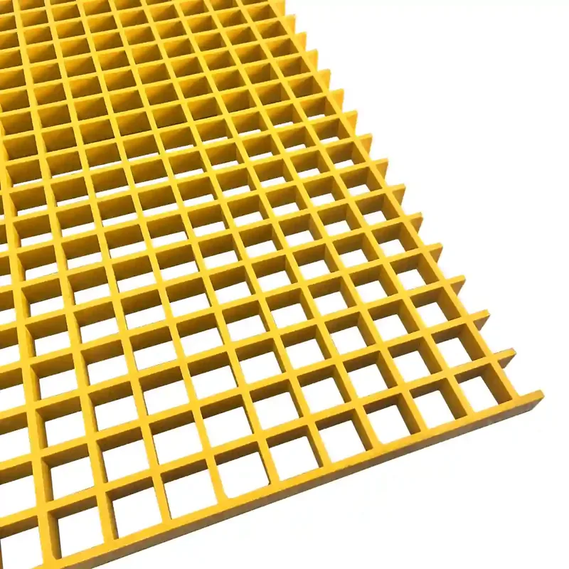

Identify the Purpose Before Drawing the Hole
An opening may be for:
- a pipe or conduit;
- cable access;
- a duct;
- maintenance access;
- lifting or equipment clearance;
- another designed penetration.
Record the object and the operating clearance. A 150 mm pipe does not necessarily mean a 150 mm cut if an annulus, sleeve, insulation or cable-bend radius is required.
This distinction separates the cut opening from the clear service opening. The finished support and edge treatment can also reduce the available opening.
Set a Datum and Dimension the Position
An opening drawing that gives only its size is incomplete. Locate the opening from fixed panel or site datums:
- two panel edges;
- a named piece corner;
- support centre lines;
- a fixed frame face.
Avoid chained dimensions across many cuts when one cumulative error can move the opening off the service. State which orientation and top face the datums belong to.
If the opening is on a replacement panel, measure the actual existing service position. Copying the old panel dimensions can repeat a historical offset.
Identify the Bars or Mesh That Are Interrupted
Molded grating is a connected grid, but a cut still removes local bars. Record:
- the opening footprint;
- the bars it passes through;
- the remaining continuous strips;
- bearing or LWO direction;
- whether the opening is close to a support;
- whether a panel joint passes nearby.
The effect cannot be judged from the cut width alone. A small opening near a narrow bearing strip may be more demanding than a larger opening in a better-supported area.
This is why the load and support review should remain separate from the cutting method.
Review the Support Around the Opening
An opening can interrupt the grid and the path to its supports. The project drawing should show:
- which supports remain;
- whether an added trimmer, frame or edge member is required;
- how that member connects to the main structure;
- which loads act near the opening;
- whether the panel is removable.
The supplier can fabricate a framing detail when the design is provided. It should not invent a load-bearing frame from a hole dimension.
The installation guide covers support measurement, panel gaps and dry-fitting.
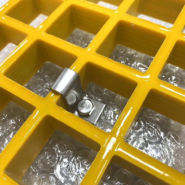
Separate Cut-Edge Sealing From Structural Reinforcement
Cutting exposes a new composite edge. Where the order requires it, the edge can be cleaned and sealed with a compatible method.
Sealing can reduce direct exposure and improve the edge appearance. It does not:
- restore a bar that was removed;
- reconnect a severed structural path;
- create bearing;
- turn an unsupported frame into a supported panel;
- make a project certificate apply to a different configuration.
The cut-edge sealing record and fabrication method explain what has been treated, cured and inspected. The structural support remains a separate design question.
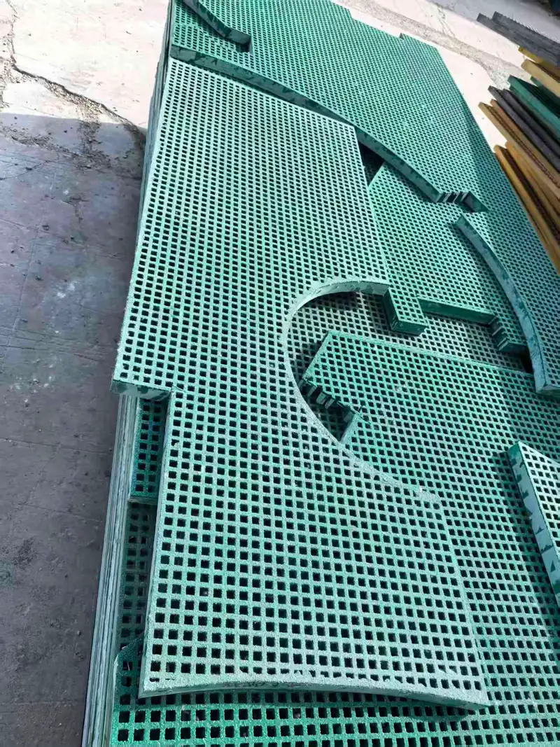
Common Opening Types
Pipe and Round Penetrations
Show the pipe outside diameter, required clearance, centre position and any sleeve or annular gap. A round hole may be cut in a range of panel positions, but the local support and mesh interruption still matter.
Rectangular Access Openings
Show the finished length, width, corner treatment, position and removable access. If the opening interrupts two directions of a molded grid, the remaining perimeter and support must be reviewed.
Notches Along an Edge
An edge notch changes the outer profile and can reduce the bearing width or remaining strip. Show it on the same plan as the supports rather than on a separate generic detail.
Multiple or Clustered Openings
Number each opening and give a common datum. A group of “small” holes can collectively remove a substantial area of the grid and create narrow ligaments that need review.
Guardrail, Post and Equipment Penetrations
A hole for a guardrail post, equipment foot or lifting point is not only a clearance cut. The post or item needs a structural connection to the supporting frame, and the cut may remove bars that were part of the walking-panel grid.
Show the post or base-plate footprint, fixing positions, connection concept, loads and support below the panel. Do not ask the hole to become the structural connection. If the item cannot bear on the frame independently, the complete assembly needs design review.
Factory-Cut Versus Site-Cut Openings
Factory cutting may be preferred when:
- the opening shape is known;
- dimensions and orientation are fixed;
- edge sealing is required;
- the opening is close to a finished edge;
- the buyer wants the piece inspected and identified before shipment.
Site cutting may remain appropriate for:
- field-measured penetrations;
- temporary construction openings;
- a hole whose position must be checked against installed services;
- an approved site fabrication scope.
Either route needs a competent cutting method and a plan for edge treatment. The factory-cut versus full-panel guide compares the commercial scope.
How to Prepare the Opening Drawing
Use a plan view with:
- the finished panel outline;
- supports and bearing faces;
- panel joints;
- every opening number;
- the finished opening size and shape;
- datum dimensions;
- required service clearance;
- interrupted-bar or LWO direction;
- any added support or frame;
- top face, piece mark and drawing revision.
A section view is useful where a pipe, collar, curb or frame changes the finished assembly.
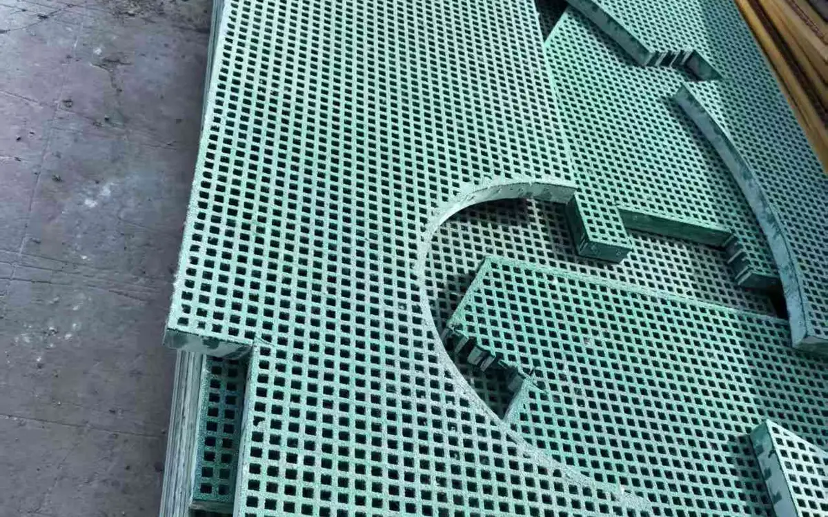
What We Can Check at the Factory
For a supplied drawing, we can review:
- whether the opening can be nested within the selected panel;
- the finished dimensions and position;
- the panel orientation;
- practical access for cutting and drilling;
- requested edge treatment;
- piece marking and packing.
Our review does not replace the responsible designer’s structural calculation or approval of the installed platform. If the support around an opening is not defined, we identify it as an open input. Where multiple penetrations, removable covers and equipment supports occur on one surface, continue with the complete installed platform review.
Installation Checks for a Cutout Panel
At receiving and installation, check:
- the piece mark and drawing revision;
- the opening size and location;
- the top face and orientation;
- whether the cut edges are clean and treated as specified;
- whether added support and framing are present;
- whether the remaining bearing is in continuous contact;
- whether fixings and clips can be reached;
- that no installation debris remains in the grid or opening.
A beautiful opening that does not match the pipe position or the support path is still the wrong piece.
If an Opening Changes After Fabrication
Changes made after cutting need a new review because the delivered piece already reflects the old opening position and the bars removed for it.
Enlarging an Existing Opening
Review the new finished shape, datum position, remaining continuous bars, support, clearance and edge treatment. The drawing must be revised before any recut. Enlargement is practical only when the new geometry and the support around it remain acceptable.
Moving or Relocating an Opening
The old opening cannot be treated as if the grid were uncut. Both the old and new positions change the local bar and load-path review. A new piece is normally safer unless an approved engineering solution covers the change.
Correcting a Wrong Orientation
The top face, mesh direction, opening datum and piece mark may all be wrong even when the hole measures correctly. Do not relabel the piece without review. Remake it when orientation is part of the design.
Patching a Hole or Damaged Bar
Resin or a cosmetic cover does not restore continuous bars, bearing or the original structural path. Replace the piece or obtain a designed repair approved for the installed condition.
This is why the factory should not treat a late site instruction as an automatic recut. A small enlargement may be possible when enough continuous bars and support remain. A moved opening, a lost bearing strip or a misplaced post connection usually requires a new piece or a properly designed support amendment.
The cutting guide covers the fabrication method, but a technically achievable cut is not automatically an approved structural change. For a replacement, return to the actual molded grating configuration before remaking the piece.
Example: Pipe Penetration Review
Assume a panel penetration is required around a pipe with:
- an outside diameter of 114 mm;
- a specified 15 mm annular clearance;
- a centre 320 mm from datum A and 610 mm from datum B;
- a support line 90 mm from the opening edge;
- a rectangular molded mesh with a required LWO direction;
- a request for sealed cut edges.
The drawing should show the nominal finished opening based on the actual design, the two datum dimensions, pipe clearance, support line, orientation and edge treatment.
The fabricator can cut the opening to that drawing. The project designer still confirms the load path around the pipe and any added support.
When We Stop a Cutout Quotation
We would pause or qualify a cut-to-size quotation when:
- the hole dimensions have no datum;
- the opening is described as “field verify” but the factory is asked to cut it;
- the service clearance is not defined;
- support around the opening is missing;
- the loaded direction or top face is unknown;
- an opening is expected to repair a damaged bar;
- edge sealing is described as structural reinforcement;
- the cut list and drawing revisions do not agree.
An incomplete opening drawing is not approved simply because a similar product photo shows a hole.
The Manufacturer Rule for Molded Grating Cutouts
Review the opening as a finished part of a supported panel. Dimension the hole, locate it from fixed datums, mark the bars and support affected, define edge treatment and carry the piece mark through fabrication.
Treat sealing as edge protection and support as a separate structural input. That division keeps a clean cut from being mistaken for a structural repair.
Factory review
How We Review a Molded Grating Cutout
The order moves from service requirement to opening map, support review, edge treatment and piece identification.
The pipe, duct, cable or access object defines the clearance and finished opening.
X and Y dimensions refer to named panel or frame references, with the top face and orientation shown.
The panel structure, support edges, remaining bars and any required added framing are reviewed together.
The drawing states which cut edges are cleaned, sealed or otherwise protected and for what purpose.
Cutting and drilling follow the approved revision, and the finished piece keeps its opening number and piece mark.
Opening size, position, edge condition, orientation, support interfaces and labels are checked against the drawing.
Fabrication experience
Where Factory Control Helps Beyond Cutting the Hole
The factory can control the cut geometry and record it, while the project designer remains responsible for the complete support condition.

Cut geometry follows a drawing
The factory needs the finished opening and location, not a photograph with an approximate arrow.
Support is not inferred
Added framing is fabricated when it is designed and specified; edge sealing is never presented as a substitute.
Orientation stays visible
The top face, LWO and opening datums remain attached to the piece through fabrication and packing.
Edge treatment has a scope
Cleaning, sealing and inspection of cut edges are stated operations, not assumptions.
Piece identification follows
Each opening is tied to a piece mark and drawing revision so similar panels cannot be swapped.
Structural approval remains separate
We can fabricate the supplied geometry; the responsible designer confirms the load path and complete platform.
RFQ checklist
What to Send for a Molded Grating Cutout Review
A marked plan, the service dimensions and the support condition belong in one review.
- Purpose and service object — Pipe, duct, cable, access opening or equipment clearance, with outside dimensions.
- Finished opening — Shape, length, width or diameter, corner/radius requirement and tolerance.
- Clearance — Required annular or inspection space, sleeve, insulation and tool access.
- Datum position — X/Y location from named panel or frame datums, including top-face reference.
- Supports and framing — Support lines, bearing faces, remaining bars and any required trimmer or frame.
- Panel configuration — Depth, pitch, mesh structure, resin, surface and full-panel size.
- Edge treatment — Which edges need cleaning, sealing, coating or another specified treatment.
- Piece identity — Opening ID, piece mark, quantity, orientation and drawing revision.
Request a review
Send Your Pipe, Cutout and Support Drawing
Provide the opening schedule and the available panel and support information.
- Opening and datum review
- Support/framing identified separately
- Edge treatment and piece mark stated
Molded FRP Grating Cutout Questions
Can I cut any size hole in molded FRP grating?
Does edge sealing restore the strength of a cutout?
How should a pipe opening be located?
What information is needed for a rectangular cutout?
Can a small opening close to a support need special review?
Can the factory add the support around a cutout?
What should be checked when a cutout panel arrives?
Can a cutout be enlarged after the panel is delivered?
Can a wrongly positioned opening be filled and recut?
This content was prepared and reviewed by Dengtai Industry’s technical and production team using the project conditions, available product data and applicable documents. Limits that require design, testing or approval are identified in the content. Content last checked: