Covered fabrication review
Coordinating Cutouts and Fixings in Covered FRP Grating
A service opening can pass through the cover and the grating base while clips hold the base to its supports. The opening, interrupted bars, added support, cover edge, fixing access and finished-piece mark must be coordinated on one drawing.
Prepared by
Dengtai Industry
Published
·
Reviewed

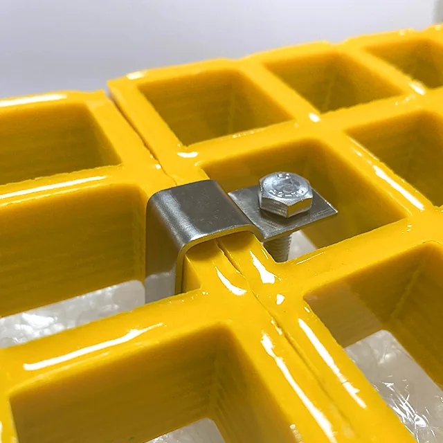
The visible top does not show whether the opening and support are coordinated underneath. Photo: Dengtai Industry.
Coordinated components
Opening, Support and Fixing Are Different Functions
The cover closes the top, the base spans, and the fixing restrains; none automatically performs the others’ jobs.
- Cutout
- A deliberate opening through a finished cover-and-base assembly for a pipe, duct, cable, service access or equipment clearance.
- Cover opening
- The opening cut through the continuous top. Its edge may need trim, sealing or additional attachment to the base.
- Base opening
- The corresponding opening through the grating grid. It interrupts bars and can change local support and load paths.
- Fixing point
- A location where a clip, bolt or other agreed device restrains the panel to its support or alignment detail. The fixing location comes from the layout, not a universal count.
- Added support
- A frame, bearer, trimmer or bearing edge introduced to carry the panel around an opening. A clip or edge seal does not replace it.
- Cover-specific fixing
- A fixing arrangement that restrains the cover separately or maintains its attachment when panels are lifted, where the assembly requires it.
- Tool access
- The clearance required to fit and tighten the clip from above or below without damaging the panel, cover or adjacent service.
Drawing matrix
One Cutout, Three Layers to Coordinate
Align cover, base and fixing information on the same datum and piece schedule.
Swipe horizontally to view all columns.
| Drawing field | Cover layer | Base grating | Fixing / support |
|---|---|---|---|
| Opening location | Coordinates from the same panel datum | Must match the cover coordinates | Bearers or added frame around the opening |
| Opening size | Finished visible opening and trim | Clear through-opening and interrupted bars | Bolt and clip clearance from the opening |
| Edge condition | Pattern continuity, trim and edge sealing | Cut-bar condition and exposed fibers | Support edge, bearing and fixing allowance |
| Panel joint | Cover joint alignment across panels | Base joint and C-clip position | Support under the joint |
| Removable access | Cover stays attached to the removable piece | Piece size remains liftable | Fixings can be released and re-established |
| Identification | Surface orientation and cover revision | Base row and bearing direction | Clip type, material and count |
Release check
When a Covered Cutout Is Ready for Fabrication
The drawing needs enough information for production and installation, not only a top-view outline.
Specify this if…
- The opening is positioned from a defined datum on both cover and base.
- The drawing shows interrupted bars and the remaining support around the opening.
- The fixing type, jaw, support and tool access can be checked.
- Cut edges, cover edges and joints have a stated treatment.
- The piece can be lifted without separating the cover from its base.
- A finished-piece mark ties the drawing, production and inspection record together.
Look elsewhere if…
- The drawing shows only a top-view outline with no underside or support.
- The cover opening and base opening are dimensioned on different datums.
- A clip is expected to support an opening edge or increase the span.
- The fixing cannot be reached after installation.
- The cover joint and base joint are not coordinated.
- Edge sealing is being used as a substitute for added structural support.
Start With the Finished Opening
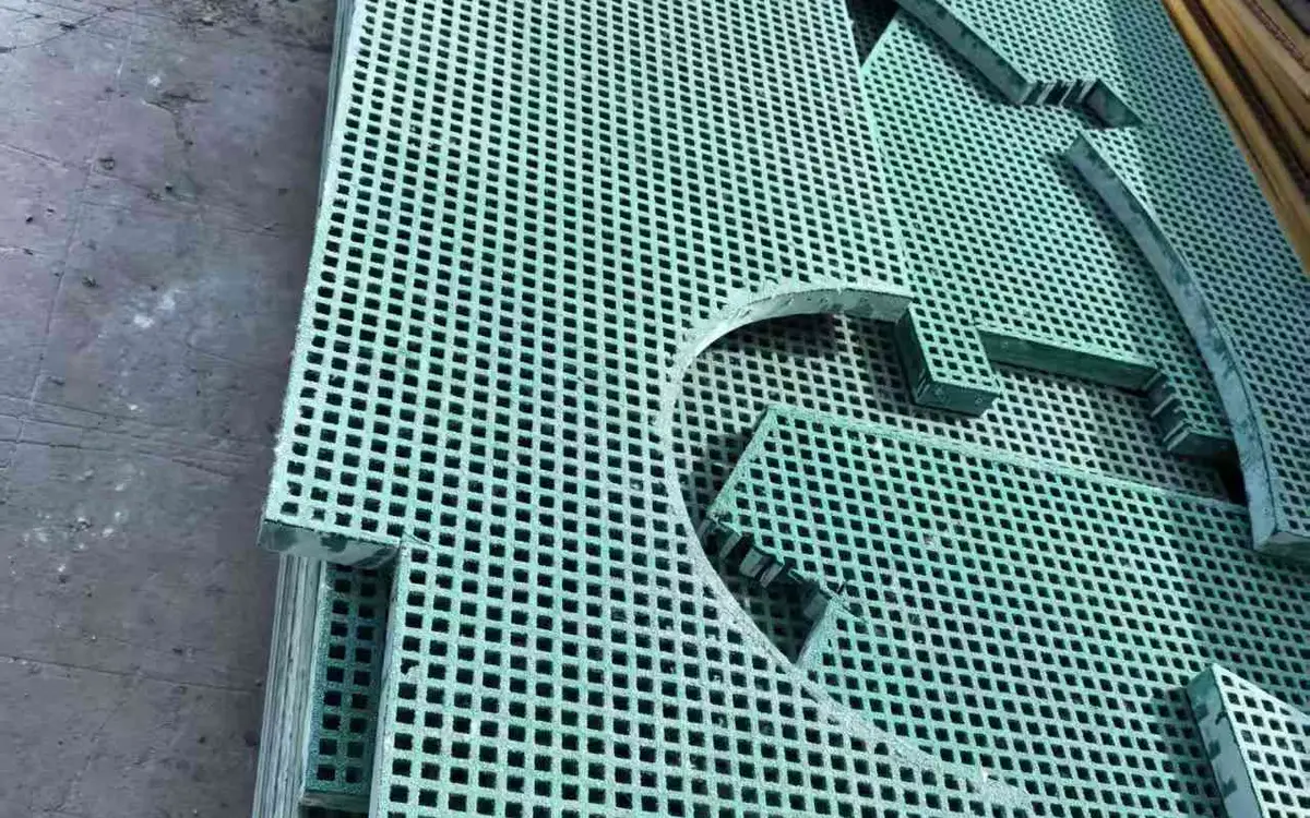
A cutout in a covered grating is not one hole in one plate. It is an opening through a finished assembly:
- the continuous cover;
- the interface between cover and base;
- the grating grid;
- any added support or framing;
- the panel edges and joints;
- the clips or other fixings.
The opening should be dimensioned from one clear datum on the panel. If the cover opening is dimensioned from the left edge and the base opening from the right edge, two drawings can look complete while manufacture is impossible.

Dimension the Opening From a Named Datum
Use an edge, centreline or approved column line as datum A and another perpendicular datum B. Record:
- finished opening type and size through each layer;
- centre or edge coordinates from A and B;
- corner radii and orientation;
- required clearance around the pipe or service;
- panel mark and revision;
- top face or bearing direction.
Round pipe openings are often specified by pipe diameter alone. That does not define the grating opening. The finished installation may need clearance for a sleeve, flange, insulation, movement, tools or a removable infill.
Check the Removed Bars
The grating base carries load through its bars. An opening removes a portion of the grid and may interrupt continuous bars. The review should show:
- which bars are removed;
- whether the opening touches a panel edge;
- how much continuous grid remains;
- where the load can reach the supports;
- whether a trimmer, frame or additional bearer is required.
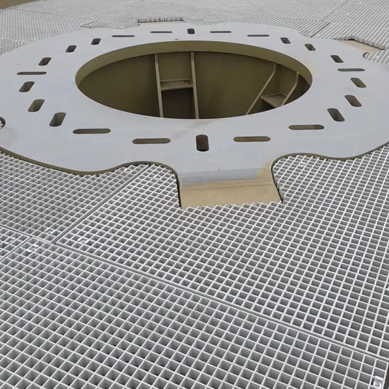
A small opening in an otherwise well-supported grid may not need a visible frame. A large opening, opening close to a free edge or opening spanning a high-load route is a different condition. There is no universal maximum opening size that can be applied without the panel and support layout. The complete structural basis belongs in the covered grating load-capacity guide.
Edge Sealing Is Not Added Support
The factory can seal a cut edge where the order requires it. Sealing protects the exposed material and is part of the corrosion and weathering detail. It does not:
- reconnect a cut bar;
- transfer load across the opening;
- turn an unsupported edge into a bearing edge;
- replace a trimmer or frame;
- prove that the opening is structurally acceptable.
State edge treatment and added support as separate lines. The cutting and sealing guide explains the fabrication boundary in more detail.
Keep Building-System Responsibility Separate
A grating opening is not automatically a firestop, waterproofing detail, gas- or liquid-tight seal, or electrical bonding point. Those are adjacent building or process systems, and each may need a different responsible designer, material and inspection record.
Coordinate them with the grating drawing rather than hiding them inside an “opening” line. The shared information may include:
- sleeve, flange and service clearance;
- firestop or penetration seal type;
- waterproofing or drainage interface;
- gasket, bonding or isolation detail;
- who inspects each interface after installation.
Our fabrication review covers the grating base, cover, cut edges and added bearing support. Unless a separate scope is agreed in writing, it does not approve another supplier’s firestop, roof membrane or sealing system.
Coordinate the Cover With the Base
The cover opening should align with the base opening within the agreed fabrication tolerance. This requires:
- the same datum coordinates;
- a common layer stack and overall height;
- the same panel orientation;
- a stated cut path through the interface;
- a cover-edge trim or sealing detail where required;
- a finished clearance that remains after all edge treatment.
If the cover is attached before cutting, the fabrication sequence must describe how the opening is made through both layers and how the interface is inspected. If they are cut separately, the registration and alignment method must be explicit.
Check the Assembled Edge, Not Only the Cut Line
The exposed edge through a covered assembly may contain:
- cover plate;
- interface;
- base bars;
- cut grid sections.
An edge seal may coat the exposed face, but the edge should remain readable for inspection. The approved sample or inspection record should show whether the edge is trimmed straight, sealed, rounded or protected by another detail.
Match the Clip Geometry to Its Actual Job
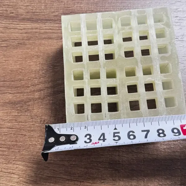
The standard clip families do different work:
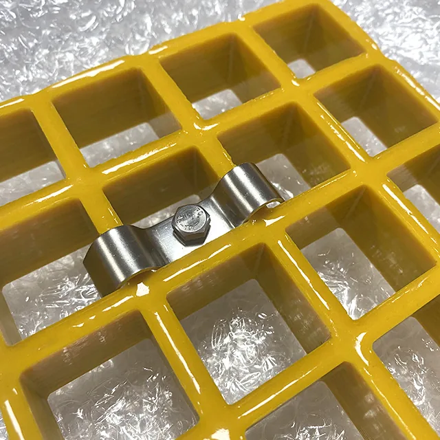
- M clips normally restrain the base across two bars to the support.
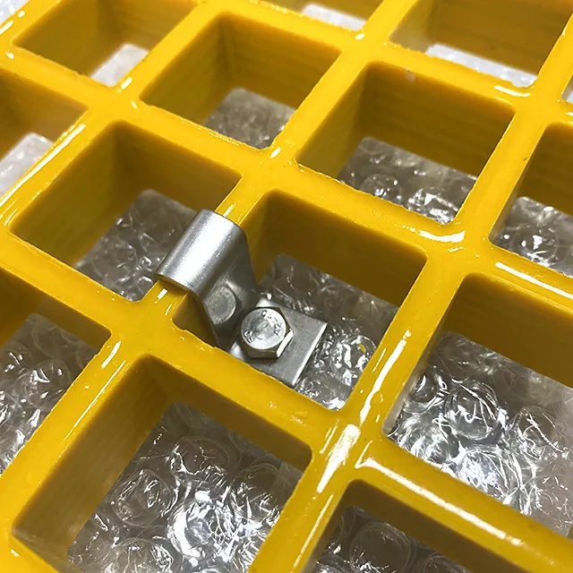
- L clips hold a single bar at lighter or restricted fixing positions.
- C clips align and restrain the edge between adjacent panels.
They are selected from the ordered panel height, bar width, support section and fixing access. A letter does not make the clips interchangeable. The cover can add a separate edge trim, interlock or fixing requirement; it is not automatically included because a base clip is in the quotation.
Other geometries may be proposed. A top-install G clip, for example, uses a different component arrangement and access path from a conventional M or L clip. Unless the quote identifies the exact product, panel fit, support fit and hardware, it cannot be assumed to match our reviewed M, L or C fixing detail.
The clips and fixings guide shows the actual fitted geometries. A clip restrains a panel; it is not a hidden structural member.
Keep Fixings Clear of Openings and Services
A fixing needs room to reach the support and tighten. Around a cutout, the fixing position may clash with:
- the opening trim;
- a pipe flange or insulation;
- the added frame;
- a cover joint;
- a later inspection or cleaning point.
Show the tool access and the finished fixing position together. A fixing dimension shown only in plan can be impossible from below because a beam, duct or support leg is in the way.
Coordinate Panel Joints and C Clips
When two covered pieces meet, two joints often coexist:
- the cover-to-cover joint;
- the base-to-base joint.
The joint may sit over a support or between supports. C clips can align and restrain a panel edge, but they do not introduce bearing. If the base joint falls between supports, the support and deflection performance must already be acceptable for that arrangement. The cover joint must align with the base movement rather than pulling the assembly apart.
Plan Removable Pieces as Complete Assemblies
If a panel containing a cutout is removable, the cover must remain attached while the piece is lifted. The design should define:
- finished-piece mass;
- lifting points;
- clip release sequence;
- whether the cover is bonded or separately fixed;
- how the piece is oriented and re-seated;
- how the edge around the cutout is protected during handling.
A large opening can leave a narrow strip or corner that is difficult to lift without twisting. The piece mark and handling instruction should be visible after packing and on installation.
Control the Opening During Service
Once a removable piece is lifted, the remaining opening becomes a temporary floor hazard. The project should plan how that condition is controlled before the first service visit:
- identify the removable piece and keep its fixing hardware controlled;
- secure the piece against accidental lift where the design requires it;
- guard or barricade the open edge while the service is exposed;
- keep tools and removed fixings from falling through the opening;
- re-seat the same marked piece and restore the complete fixing arrangement;
- follow the site’s fall-protection and permit rules.
These safety measures are site-scope decisions. The grating drawing should provide the opening geometry, removable-piece identity and fixing release method, not invent a universal guardrail design.
Verify the Production Drawing in Three Views
Plan view
Show the panel outline, joints, opening coordinates, centrelines, cover pattern direction and fixing positions.
Underside view
Show the base mesh, interrupted bars, added support and fixing access.
Section or edge detail
Show the cover thickness, interface, base, overall height, opening trim and sealing detail. Include the frame or bearer where the opening relies on added support.
The three views need the same datum and revision. A complete-looking plan with no underside is not enough.
How Our Factory Reviews the Finished Piece
Our factory works with patterned and gritted flat formats over moulded, mini-mesh and pultruded grating bases. We can review finished sizes, openings, edge treatment, piece marks and M, L or C clip requirements from the project drawing.
The quotation treats clip supply and cover-specific fixing separately. The production review checks that the opening coordinates run through the assembly and that the selected clip can engage the actual panel and support. We do not treat a sealed edge or a clip as a substitute for a missing bearing frame.
For the complete product boundary, use the covered FRP grating guide. For base-panel cutout mechanics, use the molded cutout guide.
For a wider equipment platform with several service openings, fixed panels, covers and removable pieces, use the equipment-opening and finished-piece schedule guide to extend the same datum and release discipline across the platform.
What to Send With a Cutout and Fixing Inquiry
Send:
- cover and base product configuration;
- overall height and layer section;
- plan with opening and panel joints;
- underside with interrupted bars and supports;
- added frame or bearing detail;
- fixing type, quantity and positions;
- access from above or below;
- removable-piece mass and lifting method;
- adjacent firestop, waterproofing, sealing or bonding interface;
- environment and fixing material;
- edge treatment and document scope.
A plan marked with A/B datums, five fixing positions and the underside support is usually enough to begin the review. Missing fields can be acknowledged instead of guessed.
Final Release Check
Before releasing the drawing, confirm:
- the opening uses one datum system through cover and base;
- the remaining bars and added support are shown;
- the cut-edge treatment is not treated as structural repair;
- the clip fits the panel, support and available access;
- C-clip positions align the base joint with the cover joint;
- removable pieces are liftable as complete assemblies;
- the opened area has a stated temporary protection and service sequence;
- adjacent firestop, waterproofing or sealing responsibility is shown;
- the piece mark, orientation and revision are visible.
That is the point at which the drawing can move from product discussion to fabrication.
Fabrication schedule
Covered Grating Cutout and Fixing Fields
These fields keep the opening, support and fixing in one production record.
Request a Project Quote| Specification | Value |
|---|---|
| Assembly | Covered grating type and base State moulded, mini-mesh or pultruded base; name the cover format and connection. |
| Overall height | Base, interface, cover and pattern Use the same dimension chain as the drawing and inspection record. |
| Opening | Shape, size, corner radius and coordinates Dimension both cover and base from the same datum. |
| Interrupted bars | Direction and quantity Show affected bars, remaining continuous members and added support. |
| Fixing | Confirmed clip geometry plus any cover fixing Match the named family, panel height, bar width, support, exposure and access. |
| Fixing positions | Drawing coordinates and quantity Keep clear of openings, finished edges and service access. |
| Edges | Trim, seal and bearing Cut-edge sealing protects the edge; it does not restore missing support. |
| Piece identity | Mark, revision and orientation Include removable and fixed pieces in the piece schedule. |
Send the drawing
Show Both Sides of the Opening
Include the cover top, base underside, support frame and fixing access.
- Molded and pultruded grating produced in house
- Full panels or factory cut-to-size pieces
- No fixed minimum order quantity
Covered Grating Cutout and Fixing Questions
Can a cutout be made through covered grating?
Does cut-edge sealing replace the bars removed by the opening?
Can standard grating clips be used for a covered assembly?
How many clips does a covered panel need?
Can the cover stay attached when the panel is lifted?
What causes a cutout not to fit?
This content was prepared and reviewed by Dengtai Industry’s technical and production team using the project conditions, available product data and applicable documents. Limits that require design, testing or approval are identified in the content. Content last checked: