Covered grating load evidence
Covered Grating Load Capacity: What the Complete Assembly Must Prove
A load table for an open grating does not automatically become a rating after a cover is added. Load reaches the supports through the cover, interface, base, joints and fixing arrangement. A usable capacity statement has to identify that complete system, the support and span, the load contact, the permitted deflection and the evidence behind the value.
Prepared by
Dengtai Industry
Published
·
Reviewed

The walking surface is the first part of the load path, not the whole structural product. Photo: Dengtai Industry.
Load terms
What Covered Grating Load Capacity Actually Means
Demand, configuration, deflection and evidence must be read together.
- Load demand
- The force and contact condition the installation must carry, expressed for the relevant load type and duration. It is not inferred from a generic use such as “industrial walkway” alone.
- Uniform load
- Pressure distributed across an area, commonly expressed in kPa or kN/m². The loaded area and whether self-weight is included must be clear.
- Point or foot load
- A concentrated force with a contact footprint, such as an equipment foot or a small support pad. The contact area and position relative to bars and supports matter.
- Wheel or moving load
- The load delivered through each wheel, including contact patch, routes, repeated passages, acceleration, braking and impact where relevant.
- Deflection
- The displacement of the assembly under load. A deflection limit is a serviceability requirement and can control the design even when the structure remains intact.
- Assembly load basis
- The calculation or test evidence for the complete offered construction, including cover, interface, base, support and load conditions. It must be tied to the actual geometry and assumptions.
- Ultimate load
- A failure or maximum test value under a stated procedure. It is not an allowable working load and must not be used as one without the governing safety basis.
- Allowable or design load
- The load permitted by the stated design method, standard, safety factor and limits. The exact meaning depends on the source and must be read with its conditions.
Load path
Open Grating vs a Complete Covered Assembly
A cover changes the structural question even when the base looks familiar.
Swipe horizontally to view all columns.
| Question | Open grating reference | Covered grating assembly | Why the difference matters |
|---|---|---|---|
| Structural identity | Exact panel row, mesh or bar section and depth | Cover plus interface plus base, including the complete section | The added layers change mass, stiffness and failure modes |
| Load path | Walking bars to supported edges and frame | Surface to cover, interface, base, fixings and supports | A weak connection can change behaviour before the base reaches its own limit |
| Support condition | Stated span, edges, bearing and continuity | Same fields, plus compatibility of the complete assembly | An open-panel table cannot repair unsupported edges of the finished piece |
| Load application | Uniform, point, line or wheel as defined by the source | Must match the top-cover contact and spreading condition | A uniform value does not approve a trolley wheel or equipment foot |
| Deflection | Normally read for the open panel | Should reflect the complete assembly or applicable method | Stiffness benefit cannot be assumed without a connection and evidence basis |
| Joints and openings | Panel joints and cut-outs can interrupt load paths | Additional cover joints and lifting details may add paths or discontinuities | The delivered piece, not an ideal full panel, is what the frame receives |
| Evidence identity | Product row and test or calculation conditions | Complete assembly sections, drawings and conditions | A report is only relevant when its specimen and assumptions match |
Evidence route
How to Review Covered Grating Load Capacity
Work from the project demand to the available evidence, not from a headline number backwards.
Specify this if…
- The complete assembly, support, span, load contact and deflection limit can be stated.
- The capacity evidence identifies the proposed cover, interface, base and finished geometry.
- Point, wheel or line loads are covered separately from a generic uniform-load row.
- Joints, cut-outs, fixings and removable pieces are included in the structural review.
- Temperature, duration and other service conditions have been considered.
- The responsible engineer can accept the evidence and its stated limits.
Look elsewhere if…
- The only available number comes from an open panel with no cover or interface.
- The support drawing does not show which edges bear or how the span is defined.
- A uniform-load value is being used as approval for a trolley, vehicle or equipment foot.
- The test specimen or calculation cannot be linked to the proposed construction.
- Cut-outs, weak panel joints or unsupported edges are ignored.
- The required safety basis and deflection limit are unknown but treated as satisfied.
Start With the Project Demand
The phrase “covered grating load capacity” is often treated as a product property. In practice, it is a relationship between five things:
- the load and how it contacts the surface;
- the complete covered construction;
- the span, bearing and supported edges;
- the deflection or serviceability limit;
- the calculation or test basis behind the answer.
Changing any one can change the result. That is why a quotation saying “covered grating: medium duty” or “load capacity: 5 kN/m²” cannot be accepted until the underlying conditions are visible.
The covered grating product guide explains the assembly itself. This article focuses on the structural question: what has to be proven, how to read the evidence, and where an open-panel table stops being relevant.
A Cover Changes More Than the Walking Surface
Adding a continuous layer can affect mass, stiffness, local bearing, connection and failure mode. It can also change where water, debris and maintenance loads collect.
One competitor guide describes a covered grating as about 30% stiffer than the open mesh. That statement may be accurate for that supplier’s specific construction and test conditions. It is not enough to approve another manufacturer’s assembly.
The right question is not:
“Does a cover increase capacity?”
It is:
“For this cover, this interface, this base, this support and this load case, what evidence establishes the permitted load and deflection?”
That distinction protects both the buyer and the supplier.
The interface may control behaviour
A cover can participate structurally only if the connection transfers force in the intended way. A continuous bonded interface, intermittent mechanical fixing and a loosely seated plate produce different systems. Local peeling, slip, creep or fastener movement can influence the result.
The order drawing should therefore define:
- how the cover is connected to the base;
- whether the connection is continuous or local;
- what preparation is required;
- whether the connection has to survive repeated lifting or impact;
- how joints between covered pieces are arranged;
- what inspection is performed before shipment.
Without this, “load capacity” belongs to an undefined product.
Follow the Load Path From Top Surface to Support

A typical load path is:
- Contact surface: foot, wheel, equipment foot or distributed load enters the pattern or cover.
- Cover: the continuous layer distributes or transfers the force locally.
- Interface: adhesive, interlayer or fasteners transfer load to the base.
- Grating base: the structural grid or bearing bars span toward the supports.
- Fixings and bearings: the base transfers force to the frame or structural supports.
- Support structure: the frame or beams carry the reaction into the wider platform.
Each step has a limit. A strong base cannot compensate for an unsupported cover edge. A robust cover cannot compensate for a base that is not supported along the intended span. A clip cannot be counted as a support unless it has been designed for that role.
Inspect the Interface and Its Service History
A bare strength result can miss the way a covered assembly deteriorates in service. Ask how the cover-to-base interface was controlled and what evidence exists after the specimen has experienced the expected load, temperature and handling.
The review should consider:
- Voids or incomplete contact: local lack of bond can concentrate force and create movement.
- Edge peel and shear: cover edges, cut-outs and joints may see different demands from the middle of the panel.
- Water or chemical ingress: liquid reaching a cut edge or open joint can attack the interface even when the top surface appears intact.
- Differential movement: cover, base and fixings may respond differently to temperature changes or repeated flexing.
- Repeated removal: lifting a cover at fixed points can loosen an edge, damage a mechanical fixing or progressively separate a bond.
- Surface wear and impact: exposed pattern peaks, grit and edges can wear or chip without changing the gross panel dimensions.
The inspection record should identify the section inspected, the acceptance criterion and any defects found before and after testing. A test that records only failure load but omits interface condition may answer only part of the question. The quality and documentation guide explains how to keep the drawing, inspection record and report aligned.
For heated or cyclic service, add the maximum and minimum temperature, cycle count and whether the whole assembly was conditioned together. For removable covers, record how many lift cycles are expected and how the seat, fixing and lifting points are checked. These checks should be agreed before a production assembly is accepted.
Separate Strength From Deflection
A panel can stay intact while deflecting enough to:
- feel unstable underfoot;
- interfere with doors, equipment or handrails;
- change drainage fall;
- create a trip at a joint;
- damage the cover interface through repeated movement.
The project should state its deflection limit and basis. Common project documents may use a fraction of span, an absolute limit, or both. If both are stated, both should be satisfied.
Do not use a test’s observed deflection as a performance approval and do not compare two products at different loads. A useful comparison uses the same:
- span definition;
- support arrangement;
- load pattern and units;
- load duration;
- deflection criterion.
Match the Load Type to the Evidence
Uniform load
Uniform load can suit pedestrian platforms or broadly distributed equipment. It does not describe a small equipment foot or a trolley wheel. If the load is given in kN/m², record the loaded area and whether self-weight is included.
Point or equipment-foot load
A point load still has a contact footprint. The contact geometry and position can be more important than the total weight. An equipment base with four feet carries four local loads, not one thin point at the centre of the panel.
Wheel or moving load
For trolleys, carts and vehicles, identify each wheel load, wheel width and length, route, frequency and dynamic effects. A uniform-load row is not a wheel rating. The heavy-duty grating load guide covers additional wheel, point and impact considerations.
Line load
A line load should state force per unit length, contact width, orientation and position. It may occur at a rail base, machine frame or partition.
Combined load case
Real platforms often combine self-weight, equipment, traffic and environmental actions. A single row from a table may not cover the combination. The governing project requirement should define the combinations and limits.
Check the Support Layout Before the Product
The support drawing is the foundation of the structural comparison.
Show:
- which edges are supported;
- clear span and support-centre distance separately;
- bearing width at each support;
- continuous spans versus single spans;
- panel joints and their relation to supports;
- free or unsupported edges;
- cut-outs and interrupted bars;
- positions of concentrated loads;
- how removable panels are seated and restrained.

For pultruded grating, bearing-bar direction is especially important because the main bars span in a particular direction. For moulded grating, the grid is more integrated, but the exact structure and support layout still matter. Mini-mesh is not automatically stronger because its opening is smaller.
Use the Correct Meaning of “Load Table”
A source may publish:
- measured deflection at a specific load;
- a recommended load at a deflection limit;
- a calculated allowable uniform load;
- an ultimate failure value;
- a test result under a project-specific criterion.
Those are not interchangeable. Before comparing suppliers, identify what each number represents.
Open-panel reference data
Our FRP load and span guide publishes adopted reference rows for two specific open molded structures. They show paired load and deflection values at listed spans. The tables state single-span assumptions and a safety factor from the source.
Those rows are useful for understanding the open base. They do not identify a covered assembly, a specific wheel contact or every project’s support frame.
Our factory report
We hold independent sample report HZTC/BG-24051102, issued on 17 May 2024 by Hebei Haozheng Testing Services Co., Ltd. It records multiple material and product-sample checks, including a 4 kN/m² equivalent uniform design-load test at a stated 600 mm span and appearance, hardness, water absorption, oxygen index and tensile results.
The report is valuable evidence for its named sample and test conditions. It does not identify a complete panel model with cover, interface, base, support and bearing arrangement. We therefore do not present it as a covered grating load rating.
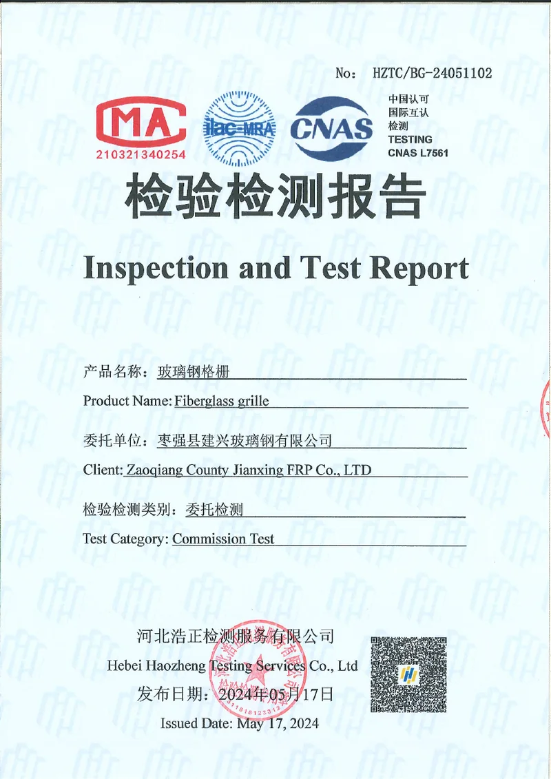
The quality and documentation guide explains how a sample report, a certificate of conformity and a project-specific test answer different questions.
A Covered Assembly Test Must Identify the Assembly
If project-specific testing is required, define the specimen before anybody tests it.
The record should identify:
- cover format, construction and thickness;
- pattern and orientation;
- interface method and preparation;
- base type, depth, pitch or bearing-bar section;
- panel dimensions and bearing direction;
- support faces, span, bearing width and fixture;
- load contact geometry and position;
- load steps, rate and duration;
- measurement points and deflection gauge method;
- failure or acceptance criteria;
- conditioning before test;
- photographs before, during and after loading.
A result without these identifiers is difficult to transfer to production. A test of an open panel is not a test of a covered assembly. A test of one cover/base combination does not approve another.
What a Supplier Should Put in a Capacity Statement
A useful statement should say more than a number:
“For the top/cover/interface/base assembly shown on drawing X, supported on two opposite edges with a clear span of Y and bearing Z, the permitted uniform load is Q at a maximum deflection of D. The basis is calculation/test T under conditions C. Point and wheel loads require separate verification.”
Or, where the evidence is narrower:
“The available test report covers the named open-panel sample, not the complete covered assembly. The present document supports the material and sample results listed in the report, but it does not establish a covered-panel capacity for this project.”
The second statement is less convenient and more trustworthy. A vendor should be able to explain what the evidence does not prove.
Compare Competing Offers With the Same Load Case
Use a fixed project row for every supplier:
| Comparison field | Project value held constant |
|---|---|
| Supports and span | Clear span, supported edges, bearing width |
| Load | Type, value, units, contact area and position |
| Deflection | Required limit and source |
| Assembly | Cover, interface and base required |
| Finished geometry | Panel sizes, joints, cut-outs and fixings |
| Service | Temperature, chemicals, duration and impact |
| Evidence | Required calculation, test or standard basis |
Then compare what each offer actually includes. Do not allow one quote to answer a full covered assembly while another returns an open-panel row with accessories excluded.
Read Marketing Claims Carefully
Common claims around covered grating include:
- higher stiffness;
- better load distribution;
- protection for what is underneath;
- reduced contamination;
- smoother traffic;
- longer service life.
Some may be valid for the supplier’s tested product. The buyer still needs to ask:
- Which construction was tested?
- What were the support and span?
- What load and contact type was applied?
- What deflection or failure criterion was used?
- Does the proposed delivered item match the tested one?
- Does the claim transfer to the actual environment and maintenance regime?
Marketing language can identify a potential benefit. It cannot replace the assembly record.
Factory Controls That Do and Do Not Prove Capacity
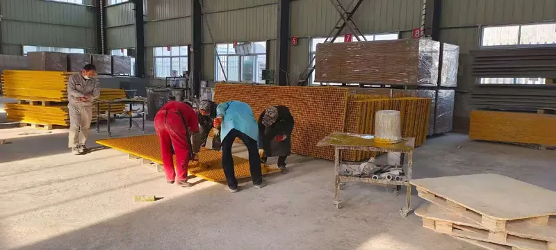
The factory’s regular appearance check covers surface flatness, cracks and blowholes. It helps catch visible manufacturing issues but is not a load test.
The factory can issue product documentation and arrange further testing case by case. For a covered assembly, the needed reach may include:
- dimensional inspection against the approved drawing;
- inspection of the cover-to-base interface;
- verification of panel marks and bearing direction;
- a project-specific structural test where specified;
- calculation review by the responsible engineer;
- packaging and handling checks for large or removable assemblies.
These are separate controls. Passing one does not automatically prove another.
Cut-Outs, Joints and Removable Pieces
A full-panel table may not describe the delivered geometry.
Cut-outs
An opening can interrupt bars and change the load path. Sealing the cut protects the exposed edge but does not reconnect a structural bar. Show the opening location and whether added framing or support is required.
Panel joints
A joint can break continuity. The bearing condition of each panel and the way loads cross the joint need to be explicit. A small plate covering the top may change the walking surface without restoring structural continuity.
Removable covers
A cover that is lifted for access needs a repeatable seat and restraint. The structural condition includes the frame, bearing, clearance and fixing when closed. Repeated handling can also affect the interface and edges.
The drain-cover guide explores frame bearing, lifting and access as one system.
Temperature, Chemicals and Time
Short-duration room-temperature evidence does not automatically establish long-term performance. Ask whether the project involves:
- sustained load;
- elevated temperature;
- thermal cycling;
- wet or chemical exposure;
- UV exposure;
- repeated wash-down;
- fatigue from moving loads;
- impact;
- fire performance requirements.
The temperature and creep guide explains why those conditions require separate evidence. Material resistance and structural capacity are related but not identical.
When the Evidence Does Not Match
If the proposed covered assembly has no applicable load evidence, do not solve the problem by adding an unsupported safety factor or copying another product’s table.
Review these options:
- Reduce demand: lower the concentrated load, change the route or restrict access.
- Improve the support: shorten the span, add supported edges or revise the frame.
- Change the assembly: review a different base, cover, interface or independent plate.
- Remove the structural need from the cover: use a supported plate or separate walkway platform.
- Arrange verification: commission a calculation or test with a defined specimen and acceptance criterion.
- Limit the claim: state exactly what the available documents support.
This is the point at which collaboration between the buyer, supplier and responsible structural engineer matters. No catalogue term should be forced to answer an engineering question it was never written to cover.
What to Send With a Covered Grating Load Inquiry

Send:
- a support plan and section;
- clear span, supported edges and bearing;
- cover and base requirements;
- any known product row;
- uniform, point, line or wheel loads with contacts;
- the deflection limit and its source;
- joint, opening and lifting details;
- service temperature, chemicals and duration;
- the required evidence and submission stage;
- the applicable project standard or specification.
If some values are unknown, mark them as unknown. Guessing a load or span can make an otherwise correct design unusable.
How Our Factory Handles This Today
Our factory can review patterned and grit flat cover formats over moulded, mini-mesh and pultruded grating bases, and quote the complete assembly from the drawing. We can provide dimensions, conformity documentation and applicable product reports, and additional testing can be arranged case by case.
What we do not do is turn an open-panel reference table or a historical sample report into a blanket covered-grating rating. That would be easy to write and impossible to defend. Instead, the project review separates:
- the construction and dimensions;
- the support and load case;
- the available evidence and its limits;
- any further verification required.
That is a slower answer at the quotation stage and a safer one at approval, fabrication and installation.
Final Approval Check
Before accepting a covered grating capacity, confirm:
- the assembly is fully identified;
- the support and span match the project;
- the load type and contact area are the same;
- strength and deflection are both covered;
- the evidence type and safety basis are explicit;
- the cover-to-base interface and edge condition are included in the evidence;
- joints, cut-outs, fixings and lifting are included;
- repeated removal, thermal cycling and other expected service history are stated;
- service conditions are not assumed away;
- the responsible engineer accepts the limits;
- the quotation and order drawing carry the same basis.
If the answer cannot survive that checklist, it is not yet a usable load capacity. It is a number waiting for context.
Send the load case
Show Us the Span, Load Contact and Assembly
A support sketch and a real contact footprint are more useful than a total weight alone.
- Molded and pultruded grating produced in house
- Full panels or factory cut-to-size pieces
- No fixed minimum order quantity
Covered Grating Load Capacity Questions
Can I use the open grating load table after adding a cover?
Does a covered grating have higher load capacity than open grating?
Is the published sample report a covered grating load rating?
What is the strongest load test evidence?
Can I compare two suppliers by asking for load capacity per square metre?
What if the project has no assembly-specific test?
This content was prepared and reviewed by Dengtai Industry’s technical and production team using the project conditions, available product data and applicable documents. Limits that require design, testing or approval are identified in the content. Content last checked: