Molded grating support guide
Molded Grating Support Layouts: Why Bidirectional Is Not Support-Free
A square molded panel distributes load through a connected grid in two directions. It still must bear on the structure at the positions assumed by the design and load data. This guide turns the frame, spans, joints and openings into a support map that can be reviewed.
Prepared by
Dengtai Industry
Published
·
Reviewed

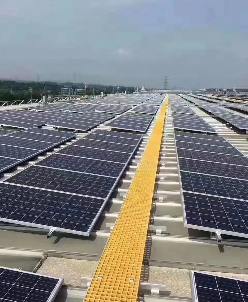
Installed molded grating on a steel support frame. The support layout and selected product row belong to the same design. Photo: Dengtai Industry.
Support terms
Supporting, Bearing and Restraining Are Different Jobs
Use the same vocabulary or a clip, joint and beam can be mistaken for one another.
- Bidirectional load distribution
- The ability of a molded grid to transfer load between bars running in two directions. It describes how the connected panel distributes force, not where the complete panel is supported.
- Support
- A beam, frame, curb or other structure that receives load from the grating and transfers it into the building or equipment structure. A clip alone is a restraint, not a support.
- Bearing face
- The measured area where the panel actually contacts the support. A support shown under the panel does not provide bearing if the contact is narrow, uneven or separated by a gap.
- Clear span
- The unsupported distance between the edges of adjacent supports. It differs from beam-centre spacing, panel length and the distance between drawings' grid lines.
- Support condition
- Whether the panel is simply supported, continuous over several supports, cantilevered or restrained in another designed way. Load data must apply to the stated condition.
- Support map
- A plan that shows every support face, clear span, panel joint, free edge, opening, load position and fixing location relevant to the grating installation.
- Panel direction
- The orientation of square or rectangular mesh and the intended top face. Rectangular mesh can have a stronger or preferred direction and must follow the approved layout.
Bidirectional myth
What Two-Way Molded Mesh Does and Does Not Prove
Distribution within the panel is not the same as the panel-to-structure load path.
Swipe horizontally to view all columns.
| Question | What bidirectional mesh supports | What still needs separate evidence |
|---|---|---|
| Can load share between bars? | Yes, the integral grid can distribute load through intersecting bars. | The panel still needs bearing points and a route for the load to reach the structure. |
| Does it work without supports? | No. No accepted molded grating becomes a supported walking surface without designed bearing. | Support positions, clear span and bearing are project design inputs. |
| Is every mesh direction equal? | Square mesh is generally less directional than rectangular mesh. | Check the selected row, mesh geometry and any stronger or LWO direction. |
| Can clips replace beams? | Clips restrain panels and control movement at an existing support. | They do not create bearing under a joint or shorten a clear span. |
| Does a joint count as support? | A panel connector can keep adjacent edges aligned. | It does not provide structural bearing unless a separately designed support exists below. |
| Can a cutout keep the original span? | The remaining grid may still carry some path around the opening. | The interrupted bars, opening position and local support need project review. |
Layout review
When a Molded Grating Support Layout Needs a Closer Check
Stop when the frame, span, joints, edges or load position are not shown clearly enough to reproduce.
Specify this if…
- Use this page when the frame or support beams exist and the actual layout must be matched to a molded panel.
- Use it when a quotation or load table assumes supports that are not clearly shown on the drawing.
- Use it when rectangular mesh, panel joints, cutouts or unsupported edges make the load path unclear.
- Use it when clips are being suggested as a substitute for missing bearing or support.
Look elsewhere if…
- Do not approve a layout from a product photograph or an assumed beam spacing.
- Do not substitute beam centres for clear spans without checking the support faces.
- Do not assume four supported sides when the drawing only shows two.
- Do not present a clip layout as proof that the panel load path is complete.
- Do not assume that a bidirectional panel can cantilever from an edge without applicable design evidence.
Support drawing
Eight Fields That Make the Support Layout Reviewable
A plan with these fields can be compared with the selected panel, load data and installation.
Swipe horizontally to view all columns.
| Layout field | Why it matters | What to show |
|---|---|---|
| Support identification | Each bearing element must be distinguishable from a panel joint or visual grid line. | Name every beam, frame, curb or plate and show its width and orientation. |
| Bearing face | The contact width and condition determine whether load can enter the support. | Show the actual flat bearing width, gaps, high points and any pad or seating detail. |
| Clear span | The unsupported distance is compared with the load table and design criteria. | Dimension between support edges separately from beam-centre spacing. |
| Support condition | A continuous, simple or cantilever arrangement does not use one assumption interchangeably. | State the structural support condition and mark any continuity assumed in the design. |
| Panel layout | Joint location and orientation affect the finished surface and local load path. | Show panel marks, joint positions, mesh orientation and intended top face. |
| Edges and openings | Free edges, trenches and penetrations may interrupt the path to support. | Mark every opening, edge notch and added trimmer or frame required by the design. |
| Fixing plan | A clip controls movement but does not create support. | Show clip type, supporting member, fixing position and any edge-distance constraint. |
| Load and evidence | Load position and the governing table or calculation must refer to the same construction. | State load type, foot or wheel footprint, deflection limit and required matched evidence. |
Bidirectional molded grating distributes load through a connected grid in two directions, but it is not support-free. The panel must still bear on a designed support, and that support arrangement must match the assumptions used to select the product row and check load and deflection.
The practical question is not whether the mesh is “strong both ways.” It is whether every load path from the walking surface reaches an actual support. A beam line, panel joint, hold-down clip and edge trimmer each do a different job.

What “Bidirectional” Actually Means
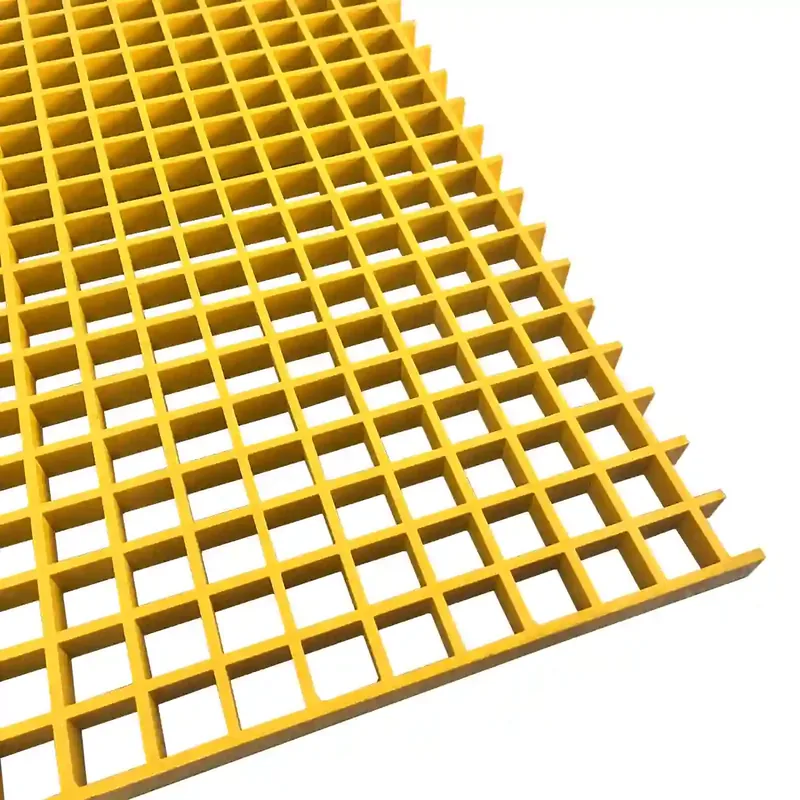
Molded grating is formed as one integral grid. Glass reinforcement and resin create bars in both directions, so a load applied on part of the surface can be shared through the surrounding mesh before it reaches the support.
That behavior has limits:
- It does not remove the need for bearing.
- It does not make every square and rectangular mesh structurally equivalent.
- It does not turn a clip into a support.
- It does not automatically approve a cantilever or a large free edge.
- It does not make the area around a cutout equivalent to an uncut panel.
Square mesh is generally less directional than rectangular mesh, but the selected product row, bar geometry and support condition still govern the calculation. The molded grating product page identifies the panel row; the load and span guide explains the conditions that must accompany the load data.
A Support Is Not Just a Line Under the Panel
An actionable support drawing contains four physical facts:
- Location: where each support sits under the panel.
- Bearing width: how much flat surface is available at the contact.
- Clear span: the unsupported distance between support faces.
- Support condition: whether the panel is simply supported, continuous over members, cantilevered or restrained by another designed arrangement.
A beam at the expected centre spacing may still be wrong if it is out of level, narrow at the top flange, separated from the panel by a packer or located under a panel joint that the drawing treats as unsupported.
The support member is part of the load path too. Do not assume it is rigid, level, continuously supported or unaffected by thermal movement, corrosion or settlement unless the project design confirms those conditions.
Do not replace measured clear spans with beam-centre dimensions. Do not treat a panel connector as a support. The installation guide covers the site checks in more detail.
Why a Clip Does Not Create Support
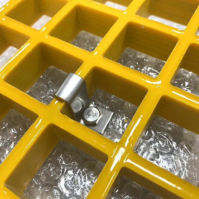
A hold-down clip connects the grating to an existing support and restrains it against lifting, sliding or vibration. It may also control movement at a panel edge. The clip does not extend the support across the rest of the span.
If the drawing shows a clip between beams and no framing below it, the panel is still unsupported at that location. If a joint or cut edge needs bearing, the design has to provide a trimmer, frame, beam or another structural member.
Match the Support Condition to the Load Data
A load table or calculation is not transferable unless its stated support condition matches the project. Compare:
- the panel construction, depth, mesh and bar geometry;
- the supported edges and clear span;
- simple versus continuous support;
- whether bearing width is stated;
- uniform, line, point or wheel load;
- load position and contact footprint;
- deflection limit;
- temperature and load duration;
- fixing and restraint assumptions.
Two supports at opposite edges and four framed edges are not interchangeable unless the evidence covers the installed condition. The approved drawing should state which edges are supported and whether the panel crosses several supports continuously.
Support Layouts You May Need to Review
| Layout | What the drawing should show | Main risk if omitted |
|---|---|---|
| Two opposite supports | Clear span, bearing faces, free edges and panel direction | A panel checked as a simple span is installed with an assumed frame or cantilever |
| Several parallel beams | Every beam, actual clear spans, continuous or simple condition and joints | Beam centres are mistaken for spans or a joint falls between supports |
| Perimeter frame | All four bearing faces, corner condition, openings and fixing plan | A gap or high point leaves one edge without effective bearing |
| Trenches and covers | Frame seats, cover lifting, bearing and removal clearance | The cover rocks, binds or relies on a clip for support |
| Local equipment frame | Footprint, point loads and support directly below them | The panel is checked for uniform load but receives a concentrated wheel or foot load |
The table is a review map, not a structural selection system. The responsible designer decides which condition applies and what evidence is acceptable.
Joints, Edges and Openings Change the Map
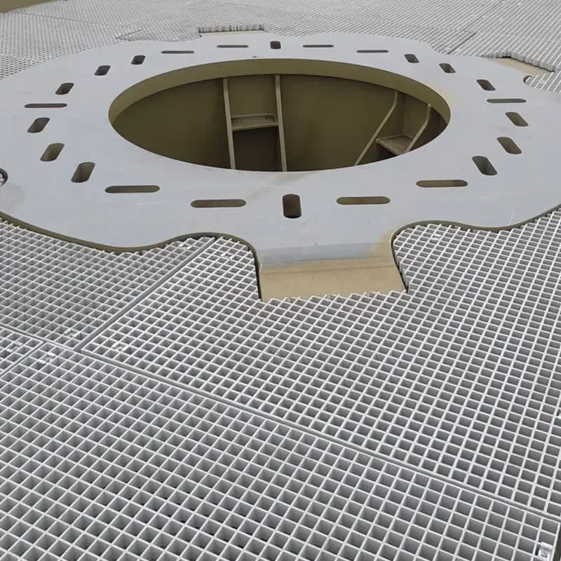
A panel joint controls the walking surface between adjacent pieces. Build a support line under the joint only where the structural design requires it. A connector that aligns two panel edges does not automatically provide bearing.
Free edges at trenches, openings and equipment penetrations need particular attention. If the panel edge is cut and no frame remains beneath it, the original support assumption may no longer apply.
Rectangular Mesh and Direction
Rectangular molded mesh can have a preferred direction even though it remains one connected panel. The stronger or designed direction, top face and joint pattern should be marked on the approved layout.
For any mesh:
- place the panel as shown on the drawing;
- keep the intended top face visible;
- show where pieces meet and which edges are cut;
- confirm the support under the affected bars;
- do not rotate a rectangular panel to make the joints fit without checking the design.
A Practical Way to Draw the Support Map
- Measure the support members that exist.
- Draw their true faces and available bearing width.
- Dimension clear spans separately from beam centres.
- Mark supported, free and cantilevered edges.
- Lay out panel marks and joints.
- Mark the mesh or stronger direction and top face.
- Add cutouts, notches and local support.
- Place uniform, point, wheel or equipment loads.
- Review the fixing positions after bearing is established.
- Send the frame, drawing revision and load case with the RFQ.
This sequence keeps structural information from being hidden behind fabrication details.
A Typical Site Example
Consider a walkway with a central longitudinal beam and cross members at intervals. The panel looks supported because it touches several steel members.
The review still needs answers:
- Is the outer edge supported or does it form a free overhang?
- Do panel joints sit over a support or between supports?
- Does the mesh direction affect the selected row?
- Is each support face wide enough?
- Does a pipe opening interrupt the grid near the beam?
- Are the clips fixing to a structural member or only joining two panel edges?
Common Support-Map Mistakes
- Using beam centres as clear spans.
- Showing panel joints but not the structure below.
- Treating the outline of a frame as continuous bearing.
- Assuming four supported edges when only two are framed.
- Using a clip to bridge a gap or support a panel edge.
- Omitting wheel, trolley or equipment-foot loads.
- Forgetting that a cutout has changed the local load path.
- Matching a load table without confirming its support and deflection assumptions.
- Treating every support member as rigid and perfectly level without checking the installed structure.
What Our Factory Can Check
For a supplied layout, our team can check:
- whether the requested pieces can be nested and fabricated;
- the panel direction and finished-piece identification;
- the opening and fixing positions shown on the drawing;
- packing and handling constraints;
- whether product information matches the requested molded row.
We do not infer a structural support that is missing from the drawing, convert a clip into a beam or approve the installed platform. Those assumptions must be resolved by the responsible project designer. When the support map belongs to an equipment floor rather than a single walkway, continue with the complete platform review to keep boundaries, equipment loads, openings and supply scope in the same selection.
What to Send With the RFQ
The most useful package is:
- one structural plan showing the frame;
- one grating layout with panel marks and joints;
- clear-span and bearing dimensions;
- load cases and deflection limit;
- mesh direction and top-face requirement;
- opening and edge-treatment details;
- fixing scope and delivery destination;
- required load table, calculation or report.
The clips and fixings guide can be used after the support map is stable. The clip type cannot resolve a missing support line.
The Manufacturer Rule for Support Layouts
A bidirectional panel can share load, but it cannot support itself. Start with the structure that exists, dimension the actual bearing and clear span, then select the grating row and evidence.
Treat joints as joints, clips as restraints and supports as the load path. That discipline prevents an apparently well-supported photograph from replacing an installation drawing.
Drawing sequence
From the Existing Frame to a Grating-Support Map
Start with measured structure and add the panel, joints, loads and fixings in a controlled order.
Measure beams, frames, curbs and bearing faces before selecting a panel layout.
Dimension the clear unsupported distance independently from beam centres and panel length.
Set panel marks, mesh direction, top face and joint lines on the same plan.
Show free edges, openings, local supports and concentrated load positions.
Compare depth, mesh, resin and support condition with the applicable load data.
Select clips for restraint and fit only after bearing and support positions are confirmed.
Factory perspective
What We Can Fabricate and What We Cannot Infer
The factory can cut and mark to an approved layout, but cannot invent the structural support condition.

We check fabricability
We confirm that the requested panels or pieces can be cut, identified, inspected and packed against the supplied layout.
We check the offered row
The depth, mesh, resin and surface must describe a product combination we can actually supply.
We identify missing input
A missing bearing face, clear span, support condition or load position is reported rather than silently assumed.
We keep clips separate
Hold-down and connector positions are reviewed as restraint details, not as substitute supports.
We preserve the drawing link
Piece and opening marks can follow the approved layout through fabrication, packing and dispatch.
The designer approves structure
The responsible project designer confirms the installed support and load path. Factory fabrication does not perform that approval.
RFQ checklist
What to Send for a Molded Grating Support Review
Send the actual frame and load information, including values that are still unresolved.
- Existing frame drawing — Beam and frame plan with member sizes, positions and available bearing faces.
- Measured clear spans — Each unsupported distance and whether the panel is simple, continuous or cantilevered.
- Panel and joint schedule — Piece marks, full-panel sizes, joint positions, mesh orientation and top face.
- Load definition — Uniform, point, line, wheel or equipment load with values, footprint and position.
- Deflection limit — The project limit and its source, including any span-ratio criterion.
- Openings and free edges — Cutouts, edge notches, trench edges and any designed added support.
- Environment and duration — Chemical exposure, normal and peak temperature, and whether loads are sustained.
- Required evidence — Load table, calculation, test report or approval criteria that the project will accept.
Request a review
Send Your Grating Layout and Support Drawing
Upload a plan showing the frame, panels, joints, clear spans, openings and load positions.
- Clear span separated from beam centres
- Joints and clips kept distinct from supports
- Openings and local load paths visible
Molded Grating Support Layout Questions
Does bidirectional molded grating need supports?
Is a molded grating panel strong in both directions?
Can a clip be treated as an extra support?
Is support spacing the same as clear span?
Does a panel joint need a support below it?
Can the factory approve the support layout?
What matters most for a support drawing?
This content was prepared and reviewed by Dengtai Industry’s technical and production team using the project conditions, available product data and applicable documents. Limits that require design, testing or approval are identified in the content. Content last checked: