Industrial platform guardrail interface
FRP Grating Openings for Industrial Guardrail Posts
This guide covers industrial FRP access platforms, not highway guardrail or scaffold standards. A platform guardrail post may pass beside or through a grating layout, but the panel should not become its structural anchorage. Coordinate the post datum, base connection, frame path, clearance opening and separate panel fixing on one drawing.
Prepared by
Dengtai Industry
Published
·
Reviewed

Guardrail and grating appear together, but their loads and approval responsibilities remain separate. Application reference: Dengtai Industry.
Separate the Post Load From the Panel Load
This page is about an industrial FRP access platform. It is not a guide to highway guardrail, vehicle barriers or scaffold standards, even though search results may use similar words. A platform guardrail post and a grating panel occupy the same edge but do not perform the same structural job. The post transfers handrail or guardrail loads through its base and anchors into a designed structure. The grating provides the walking surface and transfers floor loads to its supports.
An opening in the grating can make room for the post. It does not make the grating an anchor, and it does not make the post a panel support. This distinction should remain visible through the drawing, quotation, installation sequence and inspection.

Locate the Complete Post Base
The post centreline is only one datum. The opening layout also needs the base plate, saddle, pedestal, bolt heads, washers, anchor directions and tool access. A circular opening that fits the post can still be too small or wrongly positioned for the base connection.
Where the post sits near a panel edge, mark the panel edge and joint as well. The post opening must not force a joint to move without revising the panel schedule. If added framing is required around the opening, its member size and bearing surface belong on the structural drawing.
Compare the Main Post-Base Conditions
The grating opening follows the base connection, not only the post diameter. The main arrangements normally need to be distinguished:
- a surface-mounted base plate on a beam, curb or frame;
- a socket or pedestal connected to the structure;
- a side-mounted bracket returning into a beam or column; and
- a post integrated with a purpose-made frame or curb.
Each arrangement has a different base footprint, anchor direction, bearing surface, tool envelope and inspection route. It also changes which edge of the grating remains without support. Do not copy the opening detail from one base type to another, and do not place the grating between a post base and its structural support.
Trace the Load Into the Frame
A workable drawing shows what carries the post:
- a structural beam beneath the base plate;
- a dedicated curb or frame;
- a side bracket returning into a structural member;
- an independent support beside the grating; or
- another written connection designed for the rail reaction.
The label itself is not enough. Check that the support path is physically reachable, that the base plate has a bearing surface, that anchors can be installed and inspected, and that the grating does not sit between the post base and its support as an accidental compressible layer.
Confirm the Guardrail Design Basis
Guardrail height, post spacing, rail arrangement, anchor capacity, base-plate design and load cases are project requirements. In the United States, OSHA 1910.29 may form part of the applicable walking-working-surface requirements, while the project may also be governed by another authority, building code, owner specification or access-system standard.
The existence of one published post spacing does not make it universal. Different guardrail systems use different post sections, base plates and test bases, and a manufacturer’s installation limits apply to that system. Our grating quotation can reserve the required opening, but it does not choose the rail system, infer anchor capacity or approve the installed guardrail.
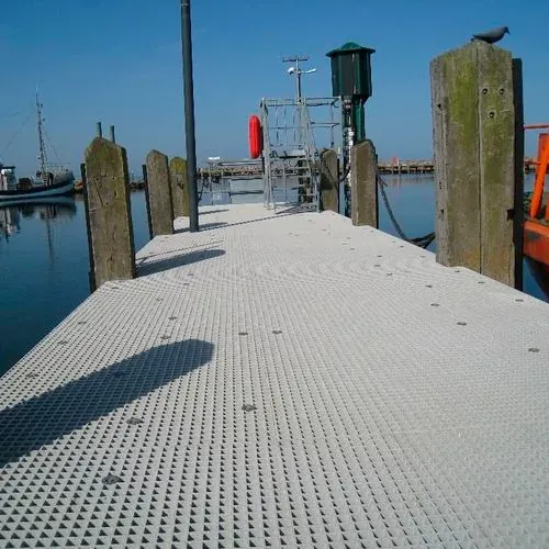
Support the Remaining Grating Edge
Cutting a post opening interrupts bars and creates a panel edge. That edge still needs a defined condition. In some layouts, the opening sits beside a frame that supports the remaining panel. In others, added framing is necessary. For pultruded grating, the bearing direction makes the interruption especially important to review.
Edge sealing protects the exposed laminate. It does not replace an interrupted bearing bar or create support under the cut edge. The cutting and sealing guide explains that boundary, while the platform grating guide covers the wider support arrangement.
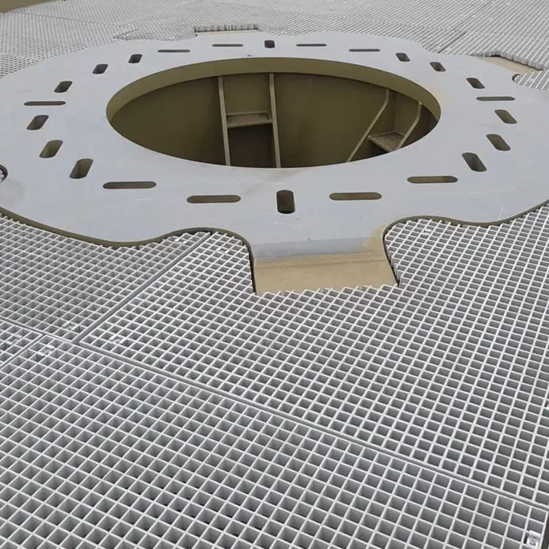

Coordinate the Grating and Guardrail Scope
The procurement package should separate:
- grating panels and finished post openings;
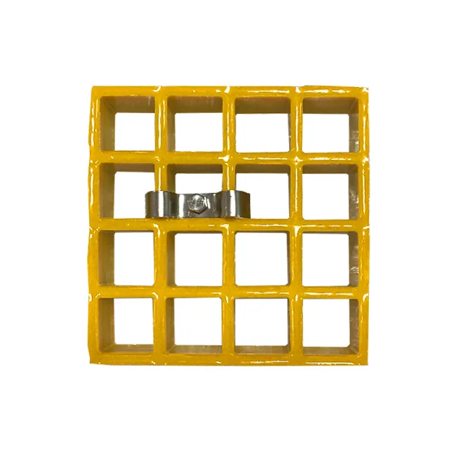
- grating hold-down and panel-joining clips;
- guardrail posts, rails, base plates and anchors;
- structural frame or added opening support;
- installation and final inspection.
One supplier may provide several of those items, but the quotation should still identify each responsibility. A combined line such as “platform and railing” can hide which party designs the frame, selects the anchors or accepts the installed system.
The factory can fabricate the controlled grating opening, treat the agreed cut edge and mark the piece. The project’s guardrail and structural design remain with the responsible engineer and installer unless separately included in a written scope.
Plan Access, Inspection and Reinstatement
The opening should leave enough access to install and inspect the post connection without cutting the panel again. A removable rail section or lift-out grating piece may be needed where maintenance access is required. In that case, mark the removable piece separately and state its restraint, handling route and reinstatement sequence.
Do not use the post as the only restraint for the covering panel. Do not use the grating clip as the only restraint for the rail. Each system keeps its own fixing and inspection criteria.
Our Factory View
We quote the grating opening from a coordinated interface drawing. The package should contain the post IDs, base envelopes, panel IDs, support member, bearing direction, added framing, edge treatment and required clip schedule.
If the post base or structural support is not defined, the opening remains open. Our factory can state what is inside the grating scope and what needs approval from the guardrail or structural designer. That explicit handoff is more useful than treating a tight field cut as engineering.
Final Release Rule
Release the opening only when the post is connected to structure, the remaining grating edge is supported, and the two fixing systems are separately identified. The grating opening provides clearance. It does not carry the guardrail.
Design References and Limits
The Fibergrate engineering guide illustrates manufacturer-specific guardrail bases, post locations, rail components and supporting structure checks. OSHA 1910.29 provides one possible regulatory basis for walking-working surfaces in the United States.
Use these references to identify the inputs that must be reviewed. They do not approve a generic post spacing, anchor, base plate or FRP platform detail, and they do not establish that the selected system complies with the governing project requirements.
Interface vocabulary
Ten Terms That Keep a Guardrail Post Separate From the Grating Load Path
A post, base, opening, frame, panel clip and anchor answer different structural questions.
- Guardrail post
- In this guide, a vertical industrial-platform member supporting handrail, guardrail or toe-board components. Its base and connections transfer rail loads into a designed supporting structure.
- Post opening
- The clearance made in the grating around a post, base plate, pedestal or connection. It accommodates the post arrangement but is not itself a structural post support.
- Base plate
- The plate, saddle, pedestal or other terminal component through which a post is connected to the structure. Its size, hole pattern and anchor envelope are part of the guardrail design.
- Post reaction
- The force transferred from the rail system through the post and base into the structural support. It is separate from the pedestrian or equipment load on the grating.
- Grating clip
- A component that holds the grating to a support or connects adjacent panels. It is not designed as the guardrail base anchorage unless the complete system has been specifically engineered that way.
- Structural frame
- The beam, curb, stringer, outrigger or fabricated support member that carries the post base and the grating supports. It may be steel, FRP or another verified construction.
- Clearance
- The gap between the post/base envelope and the cut edge of the grating. It should allow installation, inspection, movement and tools without turning a loose cutout into a connection.
- Added framing
- A secondary member that frames a larger opening or carries the remaining grating edge. It must be designed and included in the correct supply scope.
- Responsibility boundary
- The written allocation of guardrail design, structural frame, post anchorage, grating fabrication, clip fixing and installation among the responsible parties.
- Release record
- The check that the post datum, base plate, opening, added framing, edge treatment and separate grating fixings agree before panels are produced or the node is closed on site.
Post arrangements
How Different Guardrail Post Conditions Change the Grating Opening
The complete base and support path matter more than the visible post diameter.
| Post arrangement | Load path | Grating scope | Main risk |
|---|---|---|---|
| Post outside panel edge | Base connects to adjacent beam, curb or frame | Panel edge may terminate beside the post zone | A gap can grow into an unsupported walking edge |
| Post on independent base | Base plate and anchors connect to structure beneath or beside grating | Grating receives a clearance opening and separate support edge | Opening size does not prove anchor or frame capacity |
| Post through a grating opening | Post base still reaches the structural frame | Grating is cut around the post/base envelope | The cut edge may be mistaken for the post’s support |
| Post integrated with a frame/curb | Dedicated frame carries both post and nearby panel loads | Grating may terminate at or around the curb | Supply split and interface ownership can be unclear |
| Removable guardrail section | Base, socket or connector and supporting structure carry the rail | Adjacent grating remains supported independently | Removal can leave an unprotected or unsupported edge |
Panel construction
What Molded, Pultruded and Covered Panels Change Around a Post
Every product family has a different bar, opening and edge condition.
| Product condition | What to check around the post | Common wrong assumption |
|---|---|---|
| Molded grating | Remaining grid, support edges and clearance around the base | Bidirectional mesh makes every opening self-supporting |
| Pultruded grating | Bearing-bar direction, interrupted bars, added framing and post clearance | Cross rods carry the post load |
| Mini mesh | Small upper opening plus structural lower grid and edge support | A small visible mesh can be used without checking the base envelope |
| Covered grating | Cover cut, base cut, interface, edge and support beneath | A neat cover opening proves the structural layer is correct |
| Factory-cut panel | Post ID, piece ID, revision, opening shape and sealed edge | A field cut is interchangeable with a controlled factory cut |
Coordination record
The Guardrail Post Opening Record
Ten fields connect the post base, structural frame, grating clearance and responsibility matrix.
| Coordination field | Required information | Why it matters |
|---|---|---|
| Post ID | Stable reference such as P-01 or G-01 | Connects the grating opening to the right guardrail member |
| Post centre and orientation | Plan coordinates and direction relative to the platform | Sets the panel clearance and base envelope |
| Base-plate envelope | Plate, saddle, pedestal, hole and anchor access dimensions | Prevents a post opening that fits the post but not the connection |
| Structural support | Beam, frame, curb or added member that receives the base | Records where the guardrail reaction goes |
| Grating support | Separate support beneath the remaining panel edges | Keeps the walking surface independent of the post |
| Bar interruption | Bearing bars or molded bars removed by the opening | Identifies the actual structural change |
| Clearance | Required opening shape, edge condition and tool access | Allows installation without using a loose panel edge as a clamp |
| Grating fixing | M/L, C or other clip schedule at the remaining supports and joints | Keeps the panels restrained separately from the post base |
| Edge treatment | Cut-face condition, sealing and exposed-edge protection | Defines the finished edge but does not restore structural framing |
| Approval split | Guardrail, frame, anchors, fabrication, installation and inspection owners | Makes the responsibility boundary visible |
Release gates
When a Guardrail Post Opening Is Ready for Fabrication
The grating can be cut only after the complete post and support condition is defined.
Specify this if…
- The guardrail base is shown on a structural support, not on the grating itself.
- The post centre, base plate and anchor envelope are dimensioned.
- The grating opening and its support edges are shown separately.
- Interrupted bearing bars or molded grid are identified.
- Grating clips and guardrail anchors are separate line items.
- Edge treatment, tool access and inspection are defined.
Look elsewhere if…
- The opening is sized from the post diameter alone.
- The post base is assumed to clamp through the grating.
- A grating clip is treated as guardrail anchorage.
- The post location conflicts with a panel joint and no added frame is shown.
- Guardrail design, structural capacity or anchor approval is implied but not supplied.
- The field team is expected to improvise the opening on site.
Interface examples
Five Guardrail Post Conditions With Missing or Open Information
The examples show what must be resolved before a panel opening becomes a fabrication line.
| Example interface | What is known | Missing condition | Required action |
|---|---|---|---|
| GP-01 | Post centre and diameter shown | Base plate and anchor envelope absent | Do not size the opening until the full base is defined |
| GP-02 | Post sits near panel joint J-03 | Added frame and clip positions absent | Hold panel layout until the post/support node is resolved |
| GP-03 | Post base anchors to an independent beam | Grating edge support beside the opening not shown | Add separate framing and edge condition for the panel |
| GP-04 | Pultruded bearing bars interrupted by the opening | Remaining bar support and direction not addressed | Recheck the opening with the frame designer before cutting |
| GP-05 | Removable rail section noted | Reinstatement restraint and panel edge protection missing | Add the removal sequence and post service requirement |
Coordination sequence
From Guardrail Post Datum to a Released Grating Opening
Trace the load, set the clearance, separate the fixings and inspect the finished node.
Mark its centre, orientation and connection type on the platform plan.
Show the base plate, anchors or socket and the structural member that receives them.
Define the clearance opening and the support beneath the remaining grating edges.
Identify interrupted bars, preserve bearing direction and require added framing where designed.
Schedule grating hold-downs, C connectors and guardrail base hardware as distinct systems.
Apply the agreed edge treatment and inspect the opening, support, clearance and access.
Responsibility boundaries
Four Rules That Stop a Grating Opening From Becoming Post Anchorage
Physical contact, a tight cut or a panel clip does not create a structural post connection.
- Guardrail load does not become grating load — A guardrail post can receive significant lateral or impact load through its rail system. That reaction must follow the guardrail design into a structural support, not into an incidental panel cutout.
- A cutout is not a socket — Cutting grating around a post creates clearance. A socket, base plate, through-bolt or clamp creates a connection only when it is designed and fixed to an appropriate structure.
- A tight fit is not a load path — Making the opening close to the post can damage the cut edge and conceal movement. Clearance and edge protection should follow the project detail, not an assumption that contact transfers load safely.
- The factory and guardrail designer have different scopes — We can cut, finish, mark and pack the grating opening. Guardrail design, anchor selection, structural frame approval and site installation remain with the responsible parties unless a separate written scope is agreed.
Drawing checklist
What to Include With FRP Grating Guardrail Post Openings
Ten items connect the guardrail, structure, grating and installation records.
- Guardrail drawing — Post IDs, centres, orientation, base plates, anchor envelopes and rail termination.
- Structural support — Beam, curb, frame or independent support receiving each post base.
- Grating layout — Panel IDs, joints, opening locations, supports and finished walking areas.
- Product construction — Molded, pultruded, mini-mesh or covered row.
- Bearing direction — Bars or grid interrupted by the post opening.
- Added framing — Support around the opening and suitable bearing for the remaining panel.
- Clearance and edge — Opening envelope, edge sealing, inspection access and protection.
- Separate fixings — Grating clips, C connectors and guardrail anchorage scheduled independently.
- Removal and reinstatement — Any removable rail, panel, socket or access sequence.
- Responsibility matrix — Design, supply, fabrication, installation and approval owner for each interface.
Interface specification
What the Approved Guardrail Post Opening Detail Should State
The opening envelope and post support should be explicit, inspectable records.
Request a Project Quote| Specification | Value |
|---|---|
| Post datum | Centre, orientation and level The opening should follow the full connection envelope. |
| Base support | Named structural member The grating typically supplies clearance, not post anchorage. |
| Grating opening | Shape plus clearance Do not derive it from post diameter only. |
| Edge support | Separate support for remaining panel A post opening does not support the walking edge. |
| Fixing functions | Grating clip versus rail anchor Keep the two products and approvals separate. |
| Edge treatment | Defined drawing condition Cut-face protection is not structural framing. |
| Access | Installation and inspection route The post connection must remain serviceable. |
| Responsibility | Written by interface Guardrail and structural approvals are not inferred from a grating quotation. |
Platform review
Send the Post Layout and Grating Plan Together
State the base envelope, frame support, panel opening and approval ownership.
- Include the complete post base envelope
- Show support beneath both post and grating
- State guardrail approval boundaries
FRP Grating Guardrail Post Opening Questions
Does FRP grating support a guardrail post?
How large should the opening around a guardrail post be?
Can a panel clip hold the guardrail post?
Should the cut edge of the grating touch the post?
What if a post lands at a panel joint?
Does a pultruded panel opening remove load capacity?
Can the factory design the guardrail anchorage?
What belongs on the post-opening drawing?
How should a misaligned post opening be handled?
What must be included in the quotation?
This content was prepared and reviewed by Dengtai Industry’s technical and production team using the project conditions, available product data and applicable documents. Limits that require design, testing or approval are identified in the content. Content last checked: