Stair and landing layout
FRP Grating Stair Landing Layout: Tread, Nosing and Panels
A stair landing is not a rectangle measured by length and width alone. The final tread, nosing, finished level, support faces, rail posts, openings and panel joints need one common datum set. The governing stair code sets the design geometry; the factory lays out and fabricates the grating to the approved dimensions.
Prepared by
Dengtai Industry
Published
·
Reviewed

The final tread provides a key datum for the landing and guardrail layout. Photo: Dengtai Industry.
A Landing Is a Transition, Not Just a Platform
The grating at a stair landing meets several conditions at once: the last tread, the structural landing frame, the adjacent flight, guardrail posts, possible service openings and the installed walking route. A measured rectangle can be enough for a first sketch, but it is not enough to fabricate the finished pieces.
Start with one datum set. The final nosing, finished landing level, support faces, rail post positions and panel joints should be measured from references that can be traced to the structural drawing.

Measure the Final Tread With the Landing
The last tread controls the nosing and support transition into the landing. Record its width, depth, end supports, nosing line and edge construction. If the tread is a cut piece from the same grating family, record the source product and where the top face and bar direction point.
The landing’s finished level also needs a stated reference. It may relate to the final nosing, the structural frame, the adjoining floor or another project datum. What matters is that the tread and landing do not independently claim a finished level that cannot coexist.
Detail the Final Tread and Landing Surface
The transition also includes the walking surface. Record whether the final tread and landing use integrally gritted grating, an applied anti-slip treatment or an approved separate product. For an applied strip, define the profile, bonded area, edge treatment, colour and reinstatement method instead of treating colour alone as proof of slip resistance.
A formed or reinforced nosing and a separate contrast strip perform different jobs. The structural nosing closes and supports the front edge; the contrast or anti-slip element improves visual and walking cues. A strip cannot restore a weak tread end, and a coloured edge does not by itself define a slip class.
For wet service, also check how the landing drains and whether the tread-to-landing transition forms a ponding ledge. For covered or solid-top products, drainage and joint continuity need their own review.
Mark Support Faces, Not Just Beam Centres
The landing panel has to bear on something. Dimension the bearing faces and widths for the stringer ends, landing beams, perimeter frame and any added member. A centreline can be helpful for setting out, but it does not show the actual surface available for the grating edge.
Mark the clear span and direction across the landing and adjacent flights. For pultruded grating, preserve the bearing-bar run through every panel and rotation. For molded grating, identify how cutouts and panel splits interrupt the integral grid.

Check Landing Size, Headroom and the Governing Code
The required landing depth, clear width, headroom, stair rise and egress arrangement are not grating dimensions. They come from the governing building code, industrial access standard, accessibility requirement, owner specification and the stair designer’s layout. The project may use different rules for an industrial platform, a public building and a marine access structure.
Do not ask the factory to infer a code-compliant landing from a photograph or a single width and length. Supply the approved clear dimensions and the reference used for each finished level. In the United States, OSHA 1910.25 may form part of the stair-interface review, while another code or project standard may control the actual building condition.
Place Rail Posts Before Dividing the Panels
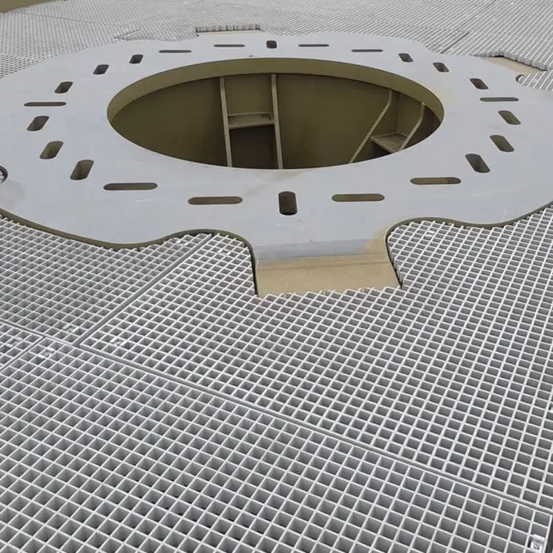
Guardrail posts can constrain where a landing panel is split. A post base may sit beside the landing edge, require a clearance opening through the panel or demand anchor access from above. If the post datum is added after the panel layout is frozen, a joint can land through the base plate or a narrow strip can be left unsupported.
The post should connect to structure, not to the grating. The landing layout should show separate supports for the post and for the remaining panel edge. The guardrail post opening guide develops that interface in detail.
Split the Landing for Support, Handling and Installation
The best panel split is not necessarily the largest one that fits the rectangle. A suitable split:
- lands on available support members;
- preserves bearing direction;
- separates awkward or handed pieces;
- keeps rail post bases and openings clear;
- allows the pieces to be carried through the access route; and
- supports future removal or service access where required.
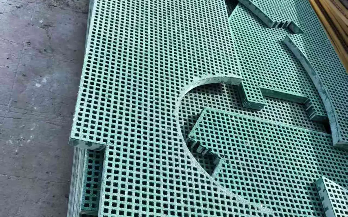
Do not create small triangular or narrow strips unless their support, edge treatment, handling and fixing are all practical. A narrow strip may be lighter, but it can be harder to secure and more likely to produce a trip or handling problem.
Tie the Piece List to the Stair Drawing
Each finished landing piece should have a piece ID, source product row, final dimensions, direction, support references, joint IDs, opening details, edge treatment, quantity and drawing revision.
Use the same marks in the quotation, inspection and packing list. Similar pieces for an upper and lower flight must not be interchangeable simply because they share a rectangular size. The factory-cut versus site-cut guide explains how the cutting route should be controlled.
Our Factory View
We can turn a measured stair and landing layout into full panels or factory-cut pieces, including agreed openings, edge treatment and marks. We can flag an unsupported joint, unresolved post base or impractical piece before production.
The factory does not approve the stair geometry, stringer design, handrail loads, anchor design or installed access system unless those are separately included. The stair tread guide and installation guide show the product and site checks that remain connected to this layout.
Final Landing Rule
A qualified landing layout shows the final tread and platform on the same datum set, supports every remaining panel edge and gives each delivered piece one traceable ID. If those records do not agree, the issue belongs in the drawing review, not in an instruction to “cut to fit” on site.
Design References and Limits
The Fibergrate engineering guide illustrates how one manufacturer relates stair treads, nosing, end support and guardrail systems. OSHA 1910.25 provides one possible regulatory reference for stairways in the United States. The Staircare stair-system overview shows how anti-slip treads, structural shapes, landings and rails can be coordinated as a complete system.
These references identify design questions and possible component relationships. They do not establish that those systems, standard editions or dimensional values apply to the current order. The governing project code and approved stair drawing remain the controlling documents.
Landing vocabulary
Ten Terms That Keep Stair Landings and Final Treads Connected
A landing is controlled by datums, support faces and piece identity, not only a plan rectangle.
- Stair landing
- The platform area at the top, bottom, turn or intermediate level of a stair system. Its grating layout must agree with the adjacent flights and supporting construction.
- Final tread
- The last load-bearing tread before the landing. Its depth, end support, nosing and level influence the transition into the landing surface.
- Landing datum
- A fixed reference used to place the landing panel, supports, openings and rail posts. Typical datums include stringer centrelines, wall faces, finished levels and post centres.
- Finished level
- The intended top elevation at the landing. It may relate to the tread nosing, structural landing frame, finish transition or other project reference.
- Stringer
- The inclined structural member supporting stair treads. Its position affects tread supports, landing framing and handrail attachment.
- Bearing face
- The actual support surface on which a tread or landing panel bears. The face location and width must be known, not inferred from a beam centreline.
- Guardrail post datum
- The centre, orientation and base-plate envelope of a rail post near the landing. It must not collide with the panel joint, cutout or edge support.
- Finished-piece ID
- A unique mark for a cut landing or tread piece, linking size, orientation, edge treatment, opening and packing to the approved drawing.
- Layout split
- The division of a full stair-landing area into panels and fabricated pieces for handling, support, joints, openings and installation sequence.
- Design boundary
- The written limit between grating layout and fabrication and the structural design of stairs, stringers, frame, guardrail, anchors and installation.
Landing conditions
How Straight, Turning and Equipment Landings Change the Panel Layout
The finished area and access route determine where the grating can be divided.
| Landing condition | Layout inputs | Fabrication consequence | Main risk |
|---|---|---|---|
| Straight flight to landing | Final tread position, stringer ends, landing frame and post centres | Main panel plus final-tread transition pieces | Landing level and nosing line are measured from different references |
| Intermediate landing with turn | Both flights, corner columns, support frame and rail posts | L-shaped or multiple panel pieces with defined orientation | Similar rectangles are rotated or installed in the wrong flight |
| Landing around an opening | Service opening, headroom, support and removable area | Narrow strips, framed edges and lift-out pieces | A large opening removes needed walking or handling area |
| Landing beside equipment | Equipment envelope, access direction, point loads and rails | Notches and removable access panels | A piece fits the outline but cannot be lifted or maintained |
| Pultruded landing | Bearing-bar direction, frame lines, panel width and support span | Panels made to direction and finished dimensions | Rotation preserves rectangle but changes the load path |
| Molded landing | Mesh direction, cutouts, edge support and finished level | Panels or nested pieces from available sheet sizes | Bidirectional grid is treated as support-free after cutting |
Product conditions
What Molded, Pultruded and Specialized Stair Pieces Require
Each landing condition still needs a product row, bar direction and supported edge.
| Stair area | Product likely to be reviewed | Don't assume |
|---|---|---|
| Final tread | Molded or pultruded load-bearing tread with defined end supports | The landing panel can be cut into a tread without tread-specific review |
| Landing field | Molded or pultruded grating matched to the landing frame | The same product and direction used for every adjacent flight |
| Nosing transition | Integral tread nosing, separate nosing or project edge detail | Any coloured edge is an approved nosing |
| Landing opening | Factory-cut opening with added framing and edge treatment | Edge sealing restores the interrupted bars |
| Rail-post area | Post base connected to structure with grating clearance | Post load can be carried by the landing panel |
Datum record
The FRP Grating Stair Landing Layout Record
Ten measured or controlled fields connect the final tread, supports, posts, openings and pieces.
| Datum field | What to measure or record | Why it controls the order |
|---|---|---|
| Landing clear size | Finished dimensions between controlling walls, frame or columns | A single nominal rectangle misses projections and tolerances |
| Final nosing | Nosing line, tread depth and top elevation | Connects the last step to the landing |
| Finished landing level | Required top-of-grating level and reference | Determines tread and landing relationship |
| Stringer/support lines | Centre or face, bearing surface and width | The panel needs support under the actual bearing line |
| Clear span and direction | Span, bar direction and support arrangement | A rectangle does not define the load path |
| Guardrail posts | Centres, base plates, anchors and access | Post positions can force panel splits and openings |
| Openings | Shape, size, location, clearance and support | A cutout changes the finished piece and walking route |
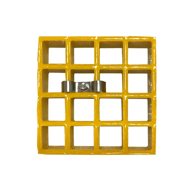
| Joining detail | Joints, clips and removable areas | Joints need support and installation sequence |
| Handling | Maximum piece size and lift route | The best-looking layout may be too large to carry |
| Revision | Approved drawing revision and piece IDs | Keeps fabrication tied to the measured condition |
Layout readiness
When an FRP Grating Stair Landing Is Ready for Fabrication
Production begins only when the stair, support and handling datums agree.
Specify this if…
- Both flights, landing and final tread are shown.
- The beam or stringer faces and bearing widths are dimensioned.
- The finished landing level and nosing relation are visible.
- Guardrail post bases and anchor access are coordinated.
- Openings and removable panels are integrated into the layout.
- Every finished piece has a mark and drawing revision.
Look elsewhere if…
- A single length and width are used as the entire stair survey.
- The last tread is omitted from the landing drawing.
- The panel is split after production because it is too large to carry.
- Post plates or their bolts overlap joints or unsupported edges.
- A pultruded panel is rotated to fill an awkward rectangle.
- The factory is expected to design the stair or rail system.
Layout examples
How Six Stair Landing Conditions Turn Into Finished-Piece Decisions
The examples show the missing measurements that can turn a simple rectangle into an unresolved package.
| Example area | Measured information | Missing link | Required action |
|---|---|---|---|
| Final tread T-01 | Width and depth noted | Nosing and both end supports are absent | Complete the tread datum before treating it as a repeatable piece |
| Landing L-01 | Clear rectangle and finished level given | Support faces and joints not shown | Divide the panel only after the support grid is fixed |
| Corner C-01 | Wall and column shown | Corner post and base plate absent | Coordinate the post before the corner panel is cut |
| Landing opening O-01 | Opening in plan | Added support and removable boundary missing | Resolve the frame before producing the surrounding pieces |
| Landing joint J-01 | Joint line drawn | Support beneath and clip condition not stated | Move or support the joint before panel dimensions are frozen |
Layout sequence
From Stair Survey to Marked FRP Grating Landing Pieces
Establish the datums, locate supports and posts, divide the area and release the piece list.
Record clear widths, travel direction, adjoining stairs, walls, columns and finished levels.
Measure tread depth, nosing, support ends and relation to the landing level.
Show stringer or landing supports by face and bearing width, not only centreline.
Add guardrail posts, equipment clearance and service openings before the panel split.
Divide the area into supported, markable and handleable pieces with consistent orientation.
Confirm the piece list, edge treatment, fixing and packing against the approved revision.
Layout boundaries
Four Rules That Prevent a Stair Landing Layout From Overpromising
Stair design, panel fabrication and installation performance have separate scopes.
- Landings are measured as a three-dimensional node — A plan rectangle does not capture the final tread elevation, nosing line, support face, rail post level or adjoining flight. The layout should record the levels and datums that control the transition.
- A panel needs support behind the cut — Every opening, edge and internal joint changes how the walking area meets the frame. Cutting the panel does not create a support under its remaining edge.
- Stair geometry remains design work — The factory can lay out and fabricate grating from the approved dimensions. Stair geometry, riser consistency, structural design, rail loads and code compliance remain with the responsible project parties.
- A landing is also a handling and access plan — Oversized pieces can be difficult to lift through a shaft or around a rail post. The panel split should account for access, future removal and spares where the project requires them.
Measurement checklist
What to Measure for an FRP Grating Stair Landing
Ten records make the landing measurable, fabricable and installable.
- Stair and landing plan — Both flights, turn direction, clear dimensions, walls, columns and equipment.
- Final tread — Position, width, depth, nosing, end supports and edge treatment.
- Finished levels — Top-of-grating and landing datums relative to the final tread.
- Support layout — Stringers, beams, landings, frame edges, bearing faces and clear spans.
- Product configuration — Molded or pultruded, depth, mesh or bar pitch, resin and surface.
- Bar direction — Direction across every flight, landing panel and changed area.
- Posts and guardrail — Post centres, base plates, anchors and clearance through the landing.
- Openings and removable pieces — Service, maintenance, headroom, lift-out panels and reinstatement.
- Piece handling — Maximum completed piece size and weight, access and lifting route.
- Revision and marks — Drawing revision, piece IDs and location code for each finished item.
Piece schedule
What the Approved Stair Landing Drawing Should State
The final schedule connects every finished piece to the measured stair condition.
Request a Project Quote| Specification | Value |
|---|---|
| Final tread | Measured as a tread, not as a landing rectangle Record nosing, depth, end supports and relation to the landing. |
| Landing level | Finished top-of-grating datum Confirm how it relates to the final tread and surrounding floor. |
| Supports | Beam face and bearing width Do not use a centreline as a substitute for the support face. |
| Direction | Recorded on every piece Pultruded bars and molded mesh orientation remain part of the identity. |
| Joints | Joint IDs plus support A panel connector alone is not joint support. |
| Post positions | Base envelope and access Grating provides clearance, not guardrail anchorage. |
| Openings | Shape, support and edge treatment Edge sealing does not restore interrupted bars. |
| Handling | Maximum piece size and weight Split the landing before fabrication when access is limited. |
Stair review
Send the Last Tread, Landing and Guardrail Layout
Include the support faces, finished levels and piece handling limit.
- Include the final tread
- Measure support faces and levels
- Mark post bases and openings
FRP Grating Stair Landing Layout Questions
How do I lay out FRP grating on a stair landing?
Which datum should control the landing?
What does the last stair tread have to do with the landing grating?
Can the factory lay out the stair landing from a sketch?
How many pieces should a landing have?
Can pultruded panels be rotated to avoid cutting?
Can a landing panel be cut around guardrail posts?
Who designs the stairs and guardrail?
What should be included in the finished-piece schedule?
How can oversized landing pieces be avoided?
This content was prepared and reviewed by Dengtai Industry’s technical and production team using the project conditions, available product data and applicable documents. Limits that require design, testing or approval are identified in the content. Content last checked: