Stair tread measurement guide
How to Measure FRP Stair Treads: Width, Depth and Nosing
Measure every tread from named edges, not from a catalogue “standard size.” Separate the stair width, support span, walking depth, going, finished thickness, nosing projection and fixing positions before a drawing is issued.
Prepared by
Dengtai Industry
Published
·
Reviewed

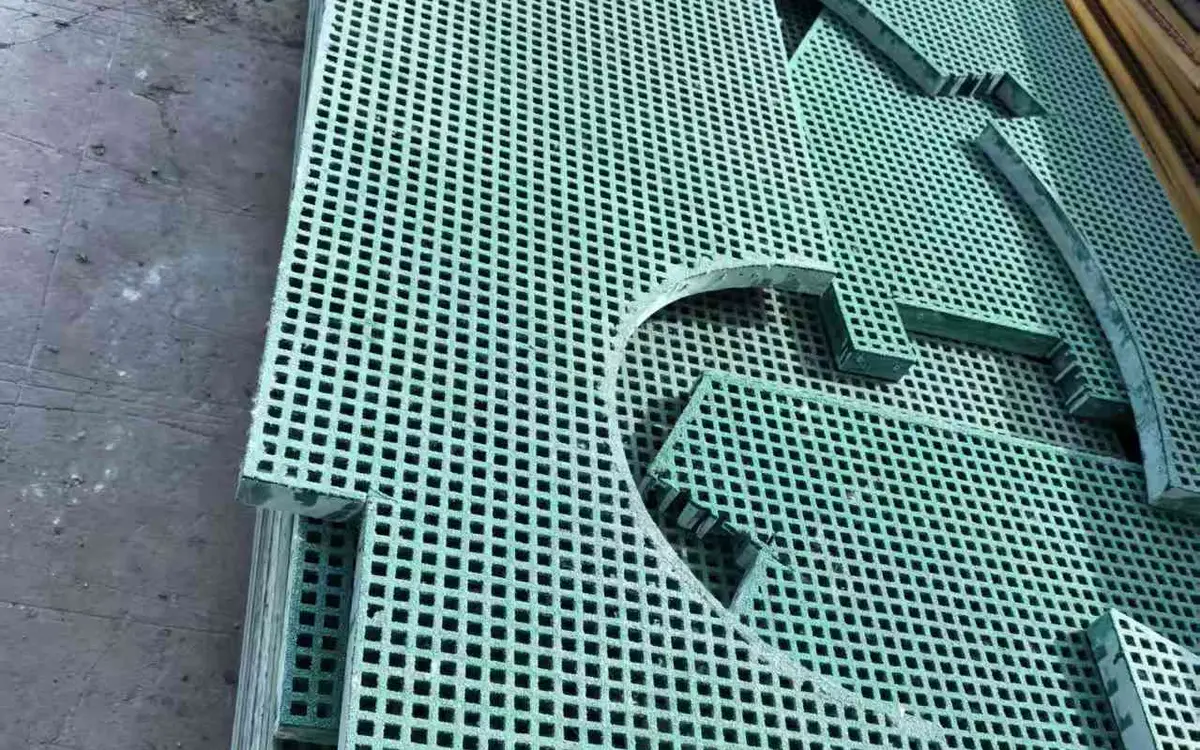
A clean overall photograph identifies the stair; measured datums identify each fabricated piece. Photo: Dengtai Industry.
Measurement vocabulary
Width, Span, Depth, Going and Thickness Are Not Synonyms
Use the same field name on the sketch, schedule, quote and inspection record.
- Stair width
- The dimension across the stair at the required datum. State whether it is measured between finished walls, outer stringers, support faces or another named reference.
- Support span
- The distance relevant to the tread load path between its left and right supports. It is not the front-to-back walking depth and it must use the support faces named by the design.
- Tread depth
- The front-to-back walking dimension of the actual tread. Mark the nose edge and the rear datum so the factory knows whether the dimension includes an overhang, return or cover layer.
- Going
- A stair geometry dimension between successive nosing lines or another agreed horizontal datum. It does not automatically equal the physical tread depth when the nose projects or the treads differ.
- Rise
- The vertical step between adjacent walking levels. A new tread or cover can change the finished level, so rise belongs to the stair survey rather than only the panel order.
- Structural depth
- The vertical depth of molded grating, pultruded bars or a complete covered assembly. It is not the front-to-back tread depth and it is not automatically the finished cover height.
- Nosing projection
- How far the front edge extends beyond the riser, substrate edge or another named datum. Record it separately from the nosing face width and the overall tread depth.
- Piece mark
- A unique identifier connecting one tread drawing to its stair, level, position, orientation, fixing layout and finished fabrication record.
Drawing release
When a Stair Tread Measurement Is Ready to Quote
The survey needs real datums, both supports, direction and a unique piece record.
Specify this if…
- Every different tread has its own measured width, depth and geometry.
- The left and right support faces, bearing width and clear span are identified.
- The front nosing edge, top face and main bar or mesh direction are marked.
- The finished rise, projection, landings and side clearances have been checked.
- The drawing uses one unit system and names each measurement datum.
Look elsewhere if…
- One “standard stair size” is expected to cover every tread.
- Stair width, walking depth and structural thickness are treated as interchangeable.
- Only one end support is shown or the support faces are not measured.
- A cover build-up is selected without checking the existing substrate and finished geometry.
- Photographs are provided without dimensions, datums, piece marks or drawing revision.
Measurement map
What Each FRP Stair Tread Dimension Controls
A complete measurement answers fit, structure, orientation and fabrication questions.
Swipe horizontally to view all columns.
| Drawing field | What to measure | Why it changes the order |
|---|---|---|
| Stair width | Across the stair at both ends and any changed middle section | Width variation can require different piece marks or edge shaping |
| Support span | Between the named support faces that carry the tread | It establishes the structural span and bar or mesh orientation |
| Tread depth | Rear datum to the front nosing edge | It controls walking depth, material use and nosing position |
| Going and rise | Horizontal and vertical stair geometry around the finished tread | They show how the tread fits the complete stair section |
| Thickness / assembly depth | Bare structural depth or finished covered assembly depth | It changes overall height, mass, fixings and support conditions |
| Nosing projection | From a named riser or substrate datum to the finished front edge | It affects trip geometry, riser clearance and finished depth |
| Fixing positions | Hole or clip locations from named left, front and top datums | They must align with bars, carriers, edge distances and tool access |
| Squareness and tolerance | Diagonal checks, edge offsets or a template where the outline is not rectangular | They tell the factory whether the opening is square and which finished dimension governs |
| Orientation | Top face, walking direction and main bar or opening direction | The same rectangle can be manufactured in the wrong direction |
Schedule fields
FRP Stair Tread Measurement Schedule
Record each dimension against an edge that another person can find.
Request a Project Quote| Specification | Value |
|---|---|
| Stair and level | Project and location ID Make every flight or isolated step traceable. |
| Tread ID | Unique piece mark Use the same mark on drawing, schedule, label and inspection record. |
| Width | Measured with named datum Record variations, wall gaps, stringer conditions and handed pieces. |
| Depth | Rear datum to nose edge State whether nose return or cover build-up is included. |
| Support | Both ends, bearing and clear span Distinguish support span from tread length or overall outside size. |
| Direction | Top-face and bearing direction Add arrows for travel, nosing and main bar or mesh run. |
| Finished geometry | Rise, going, projection and clearances Check the top and bottom landing transitions as well. |
| Squareness and size basis | Diagonals, offsets and finished dimension Do not average an out-of-square opening or add an assumed cutting allowance. |
| Fixing | Pattern, hole diameter and access Confirm the support available under each fixing point. |
Start With a Drawing, Not a Tape Measure Alone
Measuring a stair tread is not only a matter of finding one length and one width. The factory needs to know what each number describes, where it was measured and which part of the stair controls the finished piece.
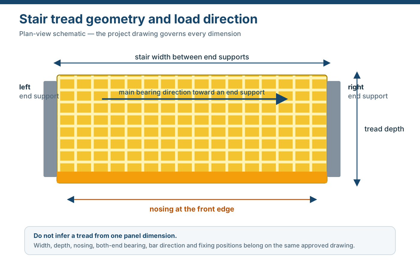
Use a simple sketch for every different tread. Mark the direction of travel, the top face, the front nosing edge, the left and right supports, the wall side and the fixing datum. Then write the measurements onto that sketch. A list of numbers without edges cannot tell the factory whether “900” is the stair width, the support span, the tread depth or the finished length.
This page deals with the measuring task. The broader selection of molded, pultruded or covered treads belongs in the complete fiberglass stair tread guide. Once the dimensions and product route are stable, use the nosing and end-detail guide to develop the carrier, projection and fixing.
In this guide
- Use one name for every dimension
- Measure every tread from named datums
- Check squareness, diagonals and finished size
- Separate replacement-tread and cover measurements
- Control orientation and piece marks
- Build a manufacturable tread schedule
- Prepare the right RFQ package

Use One Name for Every Dimension
Stair suppliers and retailers do not always use the same names. A product described as “12 × 36” may be using width, depth, length, span or overall outside size in a different order. Our drawings therefore avoid ambiguous two-number shorthand.
Stair width and support span
Start at the actual stair. Stair width describes how far the walking area extends across the stair at a stated datum. It may be measured between walls, between stringers, to the outside of a frame or between support faces.
Support span is a structural measurement. It describes the distance used to review the tread between the left and right supports. It is not automatically the same as overall length. An end may overhang beyond a carrier, one support may be wider than the other, or the clear span may differ from the distance between support centres.
Label all three where relevant:
- overall finished width;
- clear span between support faces;
- bearing width available under each end.
Tread depth and going
Tread depth belongs to the piece. Measure from the rear datum to the front edge or to the agreed finished nosing datum.
Going describes the horizontal stair arrangement. It may be measured between successive nosing lines or another design datum. The two values can differ when the nosing projects, the tread changes thickness, an existing cover is removed or the stair uses a special detail at a landing.
On a retrofit cover, the existing step depth, the cover depth and the finished projection can also differ. State what each dimension includes. If the front return wraps over the old edge, “cover depth” might include part of that return; the factory needs to know.
Thickness is not depth
A molded tread can have a structural thickness or overall panel depth. A pultruded tread is described by bar height and profile. A covered assembly includes a base and a cover layer. A retrofit cover adds a finished build-up above an existing step.
Never use “thickness” as another word for tread depth. In a stair section, record:
- the supporting stair or carrier level;
- the structural tread depth;
- the cover or walking-layer build-up;
- the finished walking level;
- the nosing projection and return.
Measure the Stair as Built, One Tread at a Time
Measure every different tread, including the first and last. Two treads that look identical in a photograph can vary at a wall, stringer, weld, repair, landing or previous cover. Mark repeated pieces only after the survey confirms that they can interchange without adjustment.
1. Identify the piece before measuring
Write the stair, flight, level and step position on the sketch before taking dimensions. For an existing stair, use the step number counted from a named landing. For a new stair, use the drawing’s tread mark or schedule ID.
Add the drawing revision and survey date. A later dimension written on an old photograph without a revision is not a controlled manufacturing record.
2. Measure width at more than one useful point
Measure across the tread support or finished width at the left end, middle and right end where access allows. Record any difference rather than silently choosing one value.
For a wall on one side, record the wall location, gap and whether the edge must follow an irregular finish. For two steel stringers, show the support faces and measure each end separately. For a wider stair, record any intermediate support or frame member even if it is not one of the two main tread ends.
3. Measure depth from a named rear datum
Place the tape from the agreed rear datum to the front nosing edge. Do not measure only the visible open mesh if a return, edge trim or cover layer continues beyond it.
Repeat the depth at the left, middle and right if the front edge or rear support is not parallel. For a curved, angled or returned piece, add enough offsets to reproduce the shape. A single overall depth may not locate the nosing.
4. Measure the supports separately
Record both end supports. For each end, show:
- support material and type;
- bearing face and bearing width;
- clear span datum;
- elevation or level difference;
- fixing or carrier position;
- access to the fixing from above or below.
This step prevents the most serious measurement error: a tread can fit the opening yet sit only on a narrow edge. A clip or bolt cannot turn that contact into full bearing.
5. Record the finished stair geometry
The tread drawing must also agree with the stair around it:
- rise between adjacent walking levels;
- going and tread depth;
- nosing projection into the riser;
- top and bottom landing transitions;
- wall, door, handrail-post and side clearances;
- any panel joining or opening that interrupts the walking surface.
A tread can meet its own length and depth while making the finished stair wrong. This is especially important when a cover adds height or when a replacement tread changes the top level.
Check Squareness, Diagonals and Finished Size
A measured width and depth do not prove that an opening is rectangular. Measure both diagonals between matching corners, or record sufficient offsets along an irregular wall, stringer or existing edge. If the diagonals differ, the opening is out of square. It should not be converted silently into one bounding rectangle.
The remedy depends on the actual interface:
- a template can capture a wall scribe, curve or local obstruction;
- recorded edge offsets can define a stepped or tapered outline;
- a larger piece can be supplied with material for an approved site fit;
- a rectangular factory piece is appropriate only when the gap or cover detail can accommodate the measured shape.
Do not average unequal end readings solely to create a convenient size. Record the left, middle and right values and identify which one controls the interface. If the buyer and factory choose a governing dimension, write that decision on the drawing.
Separate measurement, tolerance and cutting allowance
Three values must stay distinct:
- the measurement taken on site;
- the finished dimension required by the drawing;
- any rough material left for an approved fabrication or site operation.
The survey should state the unit and whether the number is measured, nominal or finished. Do not round to a familiar catalogue size unless the design accepts the resulting gap or interference. Do not add a generic “cut allowance” copied from another material; stock panel direction, saw kerf, edge treatment, holes and the actual installation detail belong to the proposed FRP piece.
When a requirement must meet a frame or wall, state the finished size and the tolerance that the interface can accept. If that tolerance has not been established, mark it open for confirmation rather than implying a precision that the site has not measured.
A practical field record can repeat the same short sequence for every piece:
piece ID → width at each datum → depth at each datum → diagonals or offsets → both supports → orientation → finished size basis → open items
That sequence is more useful than a single width, a single depth and a photograph.
A Replacement Tread and a Cover Need Different Measurements
The same stair can lead to a complete load-bearing tread or a thin retrofit cover. The selection starts with whether the existing step remains structural, as explained in the tread-versus-cover guide.
For a complete tread, measure:
- stair width and both end supports;
- clear span and bearing width;
- tread depth and nosing edge;
- main bearing-bar or molded-grid direction;
- carrier and fixing arrangement;
- required load, deflection and removal condition.
For a retrofit cover, measure:
- existing substrate depth and condition;
- cover length across the stair;
- finished cover depth and thickness;
- nosing projection over the old edge;
- adhesive or fixing positions on the real substrate;
- added height and effect on every riser and landing.
Do not use a replacement-tread survey to order a cover automatically, or a cover survey to order a new structural tread. The required fields overlap, but their structural meaning is different. The fiberglass stair tread cover guide explains that boundary in more detail.
Keep Orientation in the Measurement Record
An FRP tread is not defined by its rectangle alone. Add arrows and notes for:
- direction of travel;
- top face;
- front nosing edge;
- one or both nosing edges;
- pultruded bearing-bar direction;
- molded mesh orientation;
- cover pattern orientation;
- left- and right-hand pieces;
- fixing positions relative to bars and carriers.
This is the separate or integral nosing decision in practical form: the factory must know whether the nose is formed into the tread, produced by a cover return or attached as a separate profile.
Matching two rectangular outlines are not interchangeable if one is rotated. The wrong orientation can put the nosing on the back edge, turn pultruded cross rods toward the span or place fixings in the wrong part of a molded grid.

Build a Tread Schedule That Can Be Manufactured
A useful schedule is not a spreadsheet of widths. It is a compact fabrication record. Use one row for every different piece:
| Schedule field | Entry required |
|---|---|
| Piece mark | Unique stair, level and position ID |
| Product route | Molded tread, pultruded tread, covered tread or retrofit cover |
| Width | Measured value and direction to the datum |
| Support span | Support faces, bearing width and clear span |
| Tread depth | Rear datum to front edge, with overhang or return identified |
| Finished thickness | Structural depth or complete cover build-up |
| Nosing | Edge, construction, face width and projection |
| Orientation | Travel arrow, top face and main bar or mesh direction |
| Fixing | Pattern, hole diameter, hardware and access |
| Cutouts / edge treatment | Opening, corner, sealing or trim requirement |
| Quantity and revision | Repeated pieces only when interchangeable |
Attach the schedule to a dimensioned sketch and current stair drawing. If the schedule and drawing disagree, the quotation is not ready. The factory should not choose which number is more convenient.
The FRP sizes and definitions guide helps separate panel nominal size from actual finished dimensions. The cutting and edge-sealing guide covers openings and exposed edges after the measurements are approved.
When a Physical Template Is Useful
A template can be useful for an irregular wall, a curved outer edge, a landing return or an existing stair where the outlines vary. It supplements dimensions; it does not replace them.
Mark the template with the same piece ID, top face, nosing direction and datum as the drawing. Confirm that the template material will not distort during handling. A paper or cardboard template can show an outline while still hiding the support elevation and thickness that control the actual tread.
For repeated treads, do not make one template and assume the entire flight is identical. Compare the repeated pieces against the measured schedule. If the stair has genuine variation, create a separate mark instead of forcing an oversized piece into place.
Common Measurement Errors
- Measuring the stair once: one “representative” tread is not a complete schedule.
- Swapping width and depth: a “12 × 36” shorthand does not explain which side carries the nosing.
- Using going as tread depth: the stair datum and the physical piece are not the same field.
- Measuring only the visible opening: returns, covers, edge trims and support faces can extend beyond it.
- Missing one support: the outline may fit while the load path does not.
- Ignoring thickness: structural depth, cover build-up and finished rise can be confused.
- Forgetting direction: a rotated piece can fit but put the nose or bearing bars in the wrong place.
- Mixing units: a millimetre value entered as inches is a manufacturing error, not a rounding issue.
- Omitting the revision: a set of undated photographs and dimensions cannot be checked against the final drawing.
- Photographing without a scale: pictures help, but they do not establish a dimension.
What Our Factory Checks Before Cutting
Our first review compares the tread schedule with the stair drawing. We check that each piece has a reproducible outline, both supports are visible and the nosing, top face and main bearing direction agree.
We then check whether the proposed construction can meet the drawing: panel or bar availability, mesh and profile direction, end treatment, cover build-up, fixing access and finished piece identification. A rectangular opening is not enough to release a tread.
If the measured support span or finished geometry conflicts with the proposed tread, we mark the item open. We do not fill the gap with an assumed standard dimension or silently move a fixing into a convenient hole.
What to Send for a Measurement Review
Send the nosing and end-detail drawing or a measured sketch showing:
- stair, level and piece mark;
- measured width, depth and support span;
- both end supports and bearing width;
- rise, going, finished projection and clearances;
- top face, nosing and bearing direction;
- fixing positions and available access;
- cutouts, edge treatment and piece quantity;
- unit system and drawing revision.
Photos should be labelled to the same piece marks. If the stair is not yet built, send the controlling drawing and mark any dimension that must be confirmed on site. That is more useful than a number presented without its source.
Final Measurement Check
Before ordering, confirm:
- every different tread has been measured;
- width, support span and depth are separately named;
- going, rise and finished thickness are not hidden in one value;
- both end supports and bearing width are shown;
- the top face and bearing direction are marked;
- the nosing edge and projection are dimensioned;
- the fixing layout is reachable and agrees with the support;
- every piece has a unique mark and current revision.
That record turns a tape-measure reading into a tread that can be quoted, fabricated and checked without inventing the missing parts.
Send the survey
Send the Tread Schedule and Stair Drawing
Attach the measured schedule, photos, support detail and current drawing revision.
- Molded and pultruded grating produced in house
- Full panels or factory cut-to-size pieces
- No fixed minimum order quantity
FRP Stair Tread Measurement FAQs
How do I measure stair tread width and depth?
Is stair tread depth the same as going?
Should I measure every stair tread or assume they are identical?
What does support span mean on an FRP stair tread?
What is the difference between tread depth and thickness?
How is nosing projection measured?
What belongs in an FRP tread piece schedule?
How should I handle uneven ends, diagonals or cutting allowance?
Can a photograph replace a stair drawing?
This content was prepared and reviewed by Dengtai Industry’s technical and production team using the project conditions, available product data and applicable documents. Limits that require design, testing or approval are identified in the content. Content last checked: