Stair tread fabrication detail
FRP Stair Tread Nosing and End Details in an Order
The nosing is the front edge people approach; the two tread ends are the structural supports. Define which edge or edges carry the nosing, how it is constructed, how far it projects, where the bars bear and how the tread is fixed.
Prepared by
Dengtai Industry
Published
·
Reviewed

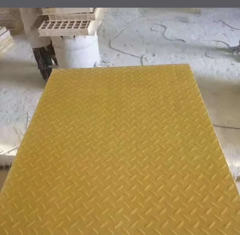
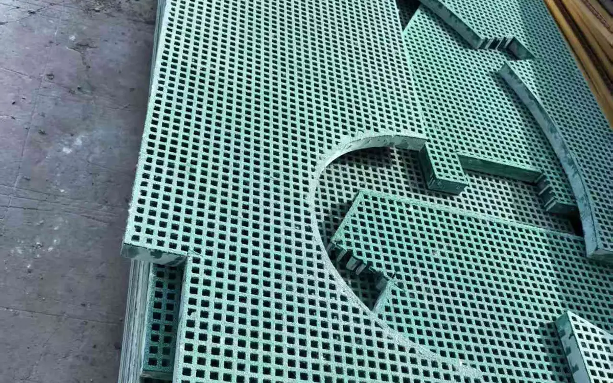
The visible nosing identifies the front edge; the approved drawing must also show both end supports. Photo: Dengtai Industry.
Detail terminology
Nosing, Edge, Support and Fixing Are Different
Define the front edge and the load path separately so neither hides the other.
- Nosing
- The front edge a person approaches when climbing. It may be formed by the tread, an applied profile, the cover return or a separate nosing product.
- Contrasting nosing band
- A visible colour or texture band at the front edge. It improves edge identification but does not automatically create structural nosing or a slip rating.
- Structural nosing
- The bar, profile, return or supported edge that carries local contact and transfers it into the tread. Its construction and support must be shown, not implied by a colour.
- Nosing projection
- How far the front edge extends beyond the riser, substrate edge or another named datum. It must be dimensioned against the finished stair section.
- Tread end support
- The stringer, angle, channel, plate or bracket at the left and right tread ends. It carries the main span and is separate from the front nosing.
- Carrier plate
- A plate or formed seat receiving a tread end. Its position, dimensions, fixing and bearing contact belong on the stair detail.
- Returned edge
- A formed or closed edge that turns down or back into the tread. It can change handling and local stiffness, but its dimension and fabrication method must be stated.
- Fixing
- A clip, bolt, screw, adhesive or combined detail that restrains the tread or cover. Fixing does not replace missing end bearing or structural nosing.
Three views
What the Tread Drawing Must Show
Plan, section and end support each answer a different fabrication question.
Swipe horizontally to view all columns.
| Detail | What it controls | Required drawing information |
|---|---|---|
| Nosing edge | Which direction people approach | Front edge, one or both long edges, orientation mark |
| Nosing construction | Structural front edge, cover return, applied profile or colour band | Formed or added detail, material, profile and attachment |
| Projection | Relationship to riser, tread depth and finished stair | Dimension, datum and tolerance |
| Tread body | Open or covered grating, depth, mesh and structure | Construction, walking depth and overall assembly |
| Left and right ends | Main load path into the stair | Carrier, bearing width, bar direction and fixing |
| Fixing | Restraint and removability | Clip or bolt type, material, position and access |
| Edges and returns | Handling, exposed laminate and fit at sides | Closed, sealed, trimmed or protected edge |
| Piece identity | Correct tread and nosing direction at installation | Mark, stair/level, revision and top-face arrow |
Detail release
When the Nosing and End Details Are Ready to Quote
The drawing needs construction and dimensions, not the phrase “nosing included.”
Specify this if…
- The nosing edge or edges are marked on the plan.
- The nosing construction is identified as structural, applied or visual only.
- The projection and finished stair geometry are dimensioned.
- Both tread ends, carrier details and bearing width are shown.
- The fixing type and installation access are defined.
Look elsewhere if…
- “Nosing included” has no edge, profile or construction.
- The nosing is expected to support the tread without a bearing path.
- A yellow strip is treated as proof of slip or fire performance.
- Only one tread end is supported, or the carrier is left undefined.
- The drawing omits piece orientation, revision or edge treatment.
Locate the Nosing Before Defining It
The nosing is the front edge a person approaches while climbing. On the plan, mark:
- the top face and direction of travel;
- the front long edge;
- whether a second long edge also has a nosing;
- the stair, level and piece mark;
- the datum for all dimensions.
A tread with two nosings can be correct in a removable or double-sided installation, but it must not be left as an accident of symmetrical fabrication. A reversed piece can fit the same rectangle and still put the nosing on the wrong side.
The two structural supports remain at the left and right tread ends. They should not be called the “front and back supports,” because that confuses the walking direction with the span.
Use the stair tread measurement guide to record width, support span, depth, going and finished thickness before the nosing section is drawn.

Identify What the Nosing Actually Is
“Nosing included” can mean several different constructions:
Formed or integral nosing
The tread or cover return is shaped at the front edge. Show the profile, face width, projection, radius or corner treatment, and how the underlying structural bars continue to support that edge.
Applied nosing profile
A separate FRP profile or covering is attached to the tread. Show its section, material, length, holes or adhesive, attachment interval and how it fits the tread edge.
Contrasting visibility band
A colour or texture band is applied or formed at the front edge. It helps identify the step. It may or may not coincide with a structural nosing or an applied anti-slip profile.
Cover return on a covered tread
The cover can turn over or finish at the front edge. The cover return changes the visible edge and may affect local stiffness, but the base bars or frame still have to carry the tread load.
These options are not interchangeable. The quotation should name the actual construction and the factory drawing should show it in section. The separate versus integral GRP nosing guide turns those choices into a product-selection comparison.
Keep the Nosing Out of the End-Support Question
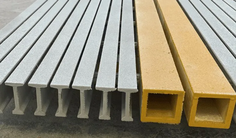
The main span runs between the left and right tread ends. Pultruded bearing bars must reach effective support at those ends. The front nosing is another edge condition.
For a pultruded tread:
- show the I, T or WT bearing-bar direction;
- show the carrier or angle at both ends;
- show bearing width and fixing access;
- show how the front nosing relates to the supported bars;
- identify any overhang or return beyond the bearing seat.
A clip or bolt can restrain the tread without creating missing bearing. A nosing profile can make the front edge visible without supporting the whole tread.
Compare the molded and pultruded structures under the same stair width, support, load and nosing condition in the molded vs pultruded stair tread comparison.

Dimension Projection Against the Finished Stair
Nosing projection is not a freestanding catalogue dimension. It interacts with:
- tread depth and going;
- riser position;
- top and bottom landing transitions;
- door and handrail clearances;
- side returns and wall gaps;
- the load case at the front edge;
- the requirement for visible contrast.
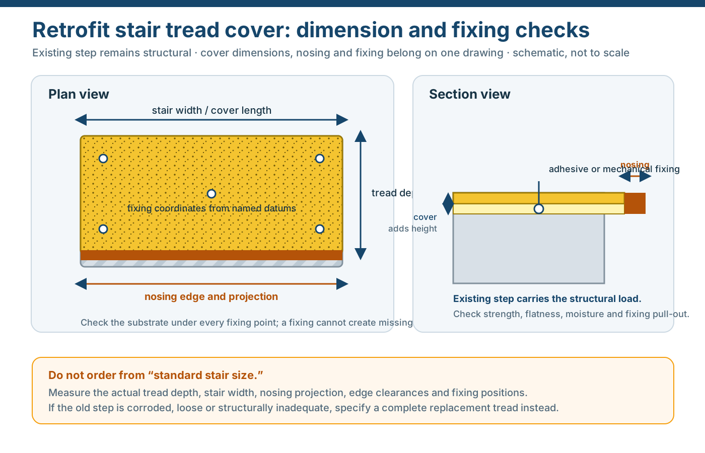
Show the projection from a named edge. If the nosing is added later, include the finished projection rather than the old substrate edge. If a cover is installed over an existing tread, add the cover thickness and nosing movement to the section.
The tread projection has to agree with the landing pieces at the top and bottom of the flight. The stair landing layout guide carries the final tread, finished level and adjacent landing panels into the same drawing revision.
There is no universal projection that can be assigned to every stair. The responsible stair or access designer confirms the finished geometry; the factory fabricates what the approved detail defines.
Define the Fixing and Removal Arrangement
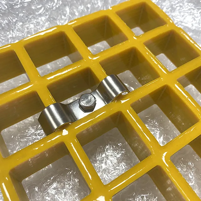
The fixing packet must say:
- clip, bolt, screw, adhesive or combined method;
- material and grade;
- washer, nut and hole details;
- hole coordinates or fixing interval;
- installation from above or below;
- whether the tread is removable;
- torque or tightening requirement when approved;
- edge distance and how the fixing avoids the nosing.
A fixing that is forced onto a bar or requires an over-sized hole is not a fit. It can distort the tread, reduce edge distance or make the nosing look correct while the support contact is wrong.
The clips and fixings guide explains the jaw and support checks.
Verify the Installation Detail Before Drilling or Bonding
A correct factory drawing still has to be checked against the actual stair before a tread is cut, drilled or bonded. Measure every tread separately; do not assume that one measured width represents a complete flight. Small variations at walls, stringers, bolted connections or repairs can change the available tread width, end contact and fixing positions from one step to the next.
Carry out a dry fit before committing the fixing:
- Record the width and tread depth at each piece, together with the stair, level and piece mark.
- Place the tread without forcing it and confirm that the nosing faces the direction of travel and that the marked top face is upward.
- Check contact at both end carriers, bearing width, nosing projection, riser clearance, landing transitions and any side gap or wall interference.
- Confirm that the fixing tool can reach every hole or clip without removing a carrier or distorting the tread.
If the dry fit is wrong, correct the measurement or the tread detail before fabrication proceeds. Do not use tightening, an oversized hole or a packed-up edge to hide missing contact.
Prepare the receiving surface
The substrate or carrier must be in the condition assumed by the approved fixing method. It should be sound, clean and dry, with loose material, contamination, corrosion products or failed previous coatings removed only by the method permitted for that substrate. For an existing stair cover, the inspection must also establish that the old step remains structurally suitable. Surface preparation does not turn a deteriorated step into a load-bearing base.
The steel, concrete and timber substrate survey lists the condition and fixing fields to record for each existing step.
If the installation method requires pre-drilling, use the approved hole coordinates or a controlled template and avoid cutting into bars, cross rods or fixing zones not intended to receive a hole. Confirm the drill diameter, edge distance and burr removal before applying a mechanical fastener. The factory should state which cuts or holes are made in production and which, if any, may be made on site.
Control adhesive and mechanical fixing
For a bonded nosing or cover, follow the product-specific method for adhesive type, mix ratio, quantity or coverage, open time, working time, clamping and cure. More adhesive is not automatically safer: excess material can create a raised edge, obstruct drainage or prevent the parts from seating. Loading, cleaning and stair reopening must wait until the specified cure condition is reached.
Where the detail uses mechanical fixing or a combination of adhesive and fixings, use the specified fastener, washer and hole size in the specified sequence. Do not replace a fastener with a larger screw, omit a fixing because the adhesive appears to hold, or add an unplanned hole through a bearing bar. The fixing restrains the tread; it does not manufacture missing bearing.
Stop and reject the fit when it is wrong
Reject or return to the detail review when the nosing sits raised or proud, rocks under hand pressure, leaves a loose end, closes the required riser clearance or changes the finished step height and landing transition. A visibly tight fastener can coexist with poor seating, an over-size hole or an unsupported edge. Tightening is not a correction for those conditions.
Inspect the completed flight as well as each individual tread. Check the alignment of the nosing line, the finished step heights through the flight, both landing transitions, exposed cut edges, debris in drainage paths and every fixing. Record any site deviation on the piece schedule so a replacement or subsequent tread is made to the same approved condition.
These checks describe the order of verification, not universal field dimensions or curing times. The exact preparation, hole, adhesive, clamp, cure and torque requirements remain specific to the supplied FRP product, substrate and approved installation method.
Treat Edge Visibility and Slip Evidence Separately
A contrasting front-edge band can improve stair visibility. It does not automatically:
- turn a plain cut edge into a structural nosing;
- establish a slip-resistance class;
- establish fire, smoke or electrical performance;
- make two different products interchangeable.
If slip or fire evidence is required, state the test method and result for the actual supplied product. If only visibility is required, state the colour, band width and construction.
If the project specifies a photoluminescent or another high-visibility nosing, identify the actual product, attachment and applicable evidence. Do not assume that every coloured or luminous band has the same charging, afterglow, durability or fire function, and do not treat a catalogue option as proof that it meets an emergency or egress requirement. Confirm availability with the proposed product rather than writing a luminous edge into a drawing by description alone.
The surface selection guide helps separate grit, pattern and other walking textures from edge visibility.
Carry the Detail Through Fabrication
A tread is ready for production when the plan, section and end view agree on:
- the front nosing edge and direction arrow;
- one or both long edges;
- the nosing construction and finished projection;
- the base construction and top face;
- both end supports and bearing width;
- the fixing and removal details;
- the edge treatment and piece mark.
The factory review checks whether the requested nosing shape can be formed or attached to the selected construction, whether the bearing bars reach the support, and whether the fixing can be reached after installation.
Read the Three Views Together
A finished tread drawing should agree in plan, section and end view:
| View | It establishes | It must agree with |
|---|---|---|
| Plan | Nosing edge, top face, width, depth and piece mark | Stair flight direction and fixing layout |
| Section | Nosing profile, cover or base layers, projection and return | Riser position, going and finished top level |
| End view | Bearing bars or grid, carrier, bearing width and fixing | Clear span, support position and removal access |
A plan can show the correct front edge while the section reveals that the nosing projects into the next riser. An end view can show a carrier while the plan places the fixings outside its bearing area. The factory should not release the tread until those views describe the same object and revision.
Use the end view to prove the load path, not only to show a bolt. The bar ends or grid must land on the carrier. If the fixing is accessed from below, show the tool path and confirm that a stringer, duct or adjacent service does not make it unreachable.
Three Ordering Examples
These examples show the fields that change; they are not standard tread sizes.
Molded tread with a front nosing
The plan marks one long edge as the nosing and marks the top face. The section defines whether the molded edge is formed, trimmed or uses a cover return. Both short ends show the stair carriers. The order adds mesh orientation, finished width and depth, fixing positions, colour contrast, edge sealing and piece mark.
Pultruded tread with a contrasting front edge
The plan marks the bearing-bar direction and the front nosing edge. The section identifies whether the visible nosing is the front of the profile, an applied part or a separate band. The end view shows both carrier seats and every bearing-bar end. The quote includes the profile, cross-rod arrangement, fixing hardware and nosing attachment separately from the visible colour.
Retrofit cover with an existing concrete step
The plan records the cover length, tread depth, nosing edge and fixing points. The section includes the existing substrate, cover thickness and finished projection over the riser. The order records who inspected the concrete, which adhesive or anchors apply and how the nosing remains supported by the existing edge. No load-bearing tread is implied.
Common Nosing Errors to Stop Before Production
- A colour called a nosing: the drawing never says whether a structural profile, cover return or applied part exists.
- A nosing on an unknown edge: the drawing has no top-face arrow or flight direction.
- A projection with no datum: the edge overhangs by a value that no one can interpret against the riser.
- End bearing hidden by clips: the fixing is detailed but the carrier and bearing width are missing.
- One end treated as representative: the drawing assumes the opposite support matches without showing it.
- A cover lip treated as support: the visible return is expected to carry the tread without a base bar or carrier.
- Colour used as performance evidence: yellow or contrasting paint is accepted as proof of slip or fire performance.
- A visually symmetric piece with no handedness: the installer can reverse a tread whose top face and nosing are not interchangeable.
The factory can correct many details before cutting, but it cannot recover a missing design decision from a finished photograph.
What the Factory Needs to Quote
Send:
- plan with nosing edge and top-face arrow;
- section through the nosing and riser;
- end-support and carrier details;
- stair width, tread depth and rise/going;
- base construction and bar or mesh direction;
- nosing construction and projection;
- fixing type, material and access;
- surface, resin and colour requirement;
- removal and piece-mark requirements;
- document and test scope.
If the nosing or carrier is not yet designed, mark it as open. The factory can identify what cannot be fabricated, but it should not invent the missing stair geometry.
Final Detail Check
Before release, confirm:
- front nosing direction is identified by an arrow and piece mark;
- one or both long edges is explicit;
- the nosing construction is not reduced to “included”;
- projection is dimensioned against the finished stair;
- both end supports and bearing width are shown;
- the fixing is separate from the bearing path;
- colour contrast and slip/fire evidence are not confused;
- cut faces, edge treatment and orientation survive packing.
That turns the nosing from a catalogue adjective into a manufacturable and inspectable tread detail.
RFQ fields
FRP Stair Tread Nosing and End Fields
These fields turn the visible front edge into a finished, identifiable tread.
Request a Project Quote| Specification | Value |
|---|---|
| Tread position | Stair, level and piece mark Distinguish repeated, handed and returned treads. |
| Nosing edge | Front edge or both long edges Include top-face and nosing direction arrows. |
| Nosing construction | Structural, cover return, applied or visual Describe the profile, material and attachment. |
| Nosing projection | Dimension from the named datum Check riser, going, landing and trip edge. |
| Tread base | Molded, pultruded or covered grating Define depth, mesh or profile and top orientation. |
| End support | Stringers, carriers and bearing width Show both ends and the clear span. |
| Fixing | Type, material, quantity and access Separate restraint from structural bearing. |
| Edge finish | Closed, sealed, trimmed or protected Identify which cut faces receive treatment. |
Send the detail
Show the Front Edge and Both Tread Ends
Include plan, section, carrier and fixing information in one request.
- Molded and pultruded grating produced in house
- Full panels or factory cut-to-size pieces
- No fixed minimum order quantity
FRP Stair Tread Nosing and End Questions
What is the difference between a stair tread nosing and the end support?
Can the nosing be on both long edges of a tread?
Is a yellow front strip the same as structural nosing?
Does nosing colour confirm slip resistance or fire performance?
How much should an FRP tread nosing project?
What end details belong on the tread drawing?
What should I send for a nosing and end-detail quotation?
This content was prepared and reviewed by Dengtai Industry’s technical and production team using the project conditions, available product data and applicable documents. Limits that require design, testing or approval are identified in the content. Content last checked: