Pultruded stair tread guide
Pultruded Stair Treads: End Support and Nosing Details
A load-bearing stair tread is more than a narrow grating panel. Confirm both end supports, the bearing-bar direction, carrier plate, nosing construction, fixing and finished-piece evidence.
Prepared by
Dengtai Industry
Published
·
Reviewed

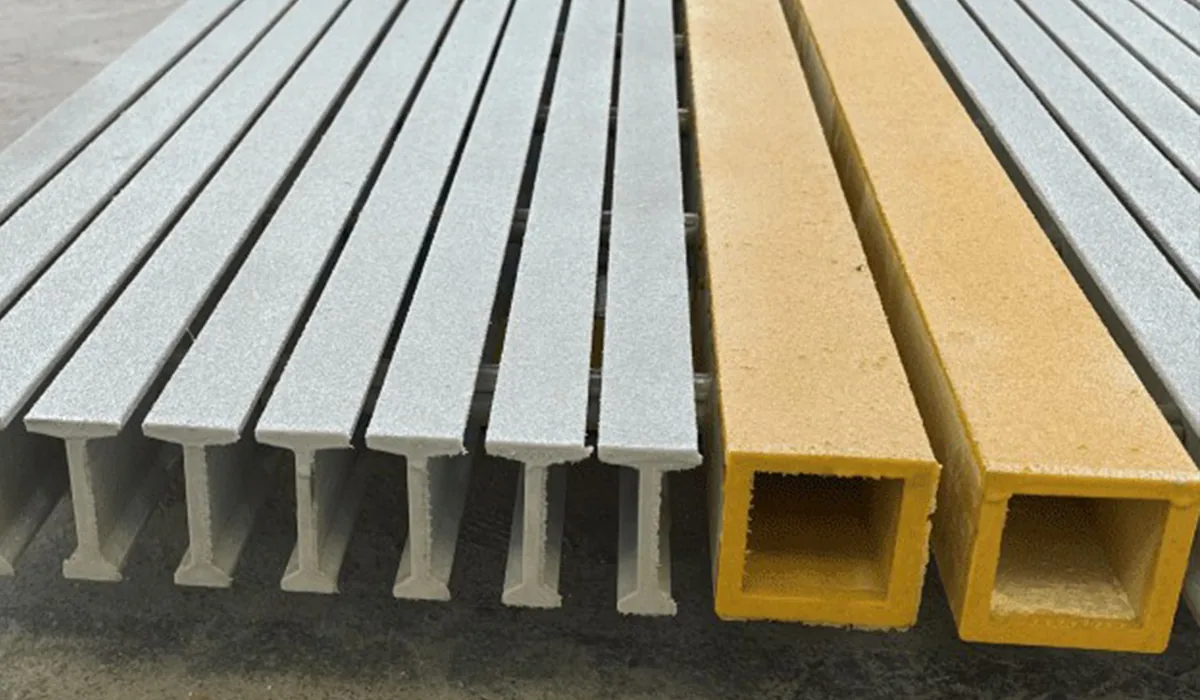
The ordered section and surface belong to the tread, but the stair span and nosing still need a drawing. Photo: Dengtai Industry.
Tread vocabulary
What a Pultruded Stair Tread Drawing Must Separate
The span, walking depth, nosing, carrier and fixing answer different questions.
- Load-bearing stair tread
- The complete step that carries people between stair stringers or brackets. Its width, walking depth, end bearing, main bar direction, nosing, fixing and surface are one assembly.
- Pultruded tread
- A tread formed from a grating assembly whose principal load path follows continuous pultruded bearing bars. It is directional; the bars must reach the designed end supports.
- End support
- The stringer angle, channel, carrier plate, cleat or bracket on which each end of the bearing bars bears. A clamps or clips may restrain the tread but do not replace missing end support.
- Carrier plate
- A plate or formed seat attached to the stair structure to receive a tread end. Its dimensions, position, connection and relationship to the fixing must appear in the stair detail.
- Nosing
- The front edge approached when climbing. It may be integrated with the tread, formed by an added profile, or protected by a separate nosing detail; the quotation must identify which construction applies.
- Tread walking depth
- The front-to-back dimension people step on. It is different from stair width, the dimension between the two end supports.
- Bearing-bar direction
- The direction in which the continuous load-carrying bars run toward their end supports. Cross rods do not become the main bearing direction because they happen to touch a carrier.
- Tread release
- The check confirming that the correct profile, direction, dimensions, ends, nosing, fixing positions, surface and required records are complete before the piece is packed.
Detail comparison
End Support and Nosing Control Different Parts of the Tread
Match each drawing field to the load path or use condition it is meant to control.
Swipe horizontally to view all columns.
| Tread feature | What it controls | Information the order needs |
|---|---|---|
| Main span | Clear distance and support positions across the stair. | Stringer spacing, bearing faces, clear span and required deflection basis. |
| Bearing-bar direction | How load travels from the walking surface to the two end supports. | I, T or WT profile, run direction and arrow or orientation mark on the drawing. |
| Walking depth | The front-to-back tread area and position of the nosing. | Finished tread depth, front and rear edge positions, overhang and tolerances. |
| Nosing | The front edge geometry, visibility, grip and local load path. | Integral or added construction, profile, projection, colour contrast and fixing method. |
| Carrier plate | The seat that receives and may locate each tread end. | Plate size, elevation, bolt or weld detail, drainage and relationship to the bar ends. |
| Hold-down fixing | Restraint against lifting, sliding or movement during use. | Clip, bolt, washer, material, position and removal requirement. |
| Open area | Drainage, debris passage and the walking contact around openings. | Pitch and clear opening can change cleaning and underfoot behaviour without changing the span direction. |
Drawing fields
Eight Fields for a Pultruded Tread Review
Record the geometry, section, direction, support and finished-piece evidence together.
Swipe horizontally to view all columns.
| Drawing field | What to show | Why it matters |
|---|---|---|
| Tread identity | Stair, flight, tread mark, quantity and drawing revision. | Similar treads can differ by depth, nosing or fixing position. |
| Overall geometry | Finished width, walking depth, stair angle and nosing projection. | A tread cut from a panel must still match the stair route. |
| Section row | I, T or WT family, depth, pitch, top width and cross-rod basis. | The pultruded structural identity is more than tread thickness. |
| Bar direction | Arrow from one end support to the other. | The bars must span between stringers or brackets as designed. |
| End seats | Carrier plate, angle or channel dimensions and bearing width at each end. | Both ends of the main bars must reach effective support. |
| Nosing construction | Integral or added profile, section, projection, colour and grip surface. | The drawing identifies the part that the quotation and production will follow. |
| Fixing | Clip or bolt type, material, positions, hardware and removal requirement. | Restraint is separate from end bearing. |
| Release evidence | Edge treatment, piece mark, dimensional check, report scope and packing requirement. | The supplied tread remains traceable from drawing to delivery. |
A pultruded fiberglass stair tread is a directional load-bearing assembly, not a narrow platform panel with an edge painted yellow. It becomes an orderable tread only when the drawing connects the stair span, both end supports, bearing-bar direction, walking depth, nosing construction, fixing and surface.
The most common failure is not choosing the wrong profile name. It is allowing a stock-looking tread size to stand in for a measured stair condition.

Start With the Span Between the Stringers
Measure the clear span and the bearing seats, not the outside dimensions of the stair. Both ends of every principal bearing bar must reach an effective support.
Record:
- the stringer, angle, channel or carrier-plate faces;
- the clear distance between those faces;
- the available bearing width at each end;
- the elevation and squareness of the seats;
- the fixing access above, below or beside the tread;
- whether the tread is fixed, removable or replaceable.
A tread can fit between two stringers and still be wrong if the ends sit on a high weld, miss the carrier plate or only touch through a clip. Dry fitting the measured steelwork is more reliable than assuming a nominal stair width.
The bearing-direction guide explains how to carry the span arrow and piece identity from drawing to installation.
Separate Width, Walking Depth and Nosing Projection
Stair-tread catalogues use “width”, “depth”, “length” and “span” in different ways. For procurement, name every edge.
- Tread span or stair width: the dimension between the two end supports.
- Walking depth: the front-to-back surface underfoot.
- Nosing projection: the distance the front detail extends or returns beyond the walking plane.
- Back edge: the rear cut edge and its relationship to the next riser or frame.
Dimension from one stated datum. Show the nosing edge and the bearing-bar arrow on the same view. A drawing that gives only a rectangular outline still leaves the fabricator guessing which side is the front and which direction carries load.
Decide How the Finished Tread Comes From the Pultruded Run
Some suppliers describe standard long tread panels that are cut to the stair width. That can be a useful production reference, but it is not a universal size or a structural approval for every pultruded row.
For our custom order, the quotation follows each finished tread mark. The fabrication review should establish:
- whether the required tread can be produced without an unacceptable joint in a principal bearing bar;
- how the source width, bearing-bar length, pitch and cross-rod layout align with the walking depth;
- where cutting loss and offcuts fall;
- how both ends, the nosing and fixing positions follow from the same datum;
- whether the piece can be lifted, packed and installed without a handling split;
- which cut faces require resin edge sealing.
Do not assume that a tread removed from a long grating run is interchangeable with one formed to a different layout. A butt joint or sealed cut is not a substitute for continuous load-bearing bars unless the connection and load path are separately designed and approved.
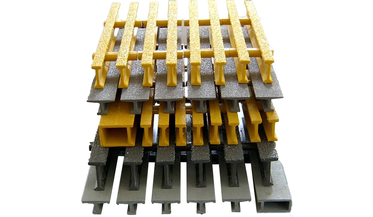
Orient the Bearing Bars Across the Intended Span
On a conventional stair between two side stringers, the pultruded bearing bars normally cross from one side support to the other. Cross rods stabilize the assembly but do not replace that principal span.
Check the drawing for:
- an arrow or note showing the bearing-bar direction;
- continuous bars reaching both end seats;
- the I, T or WT profile and pitch;
- cross-rod positions relative to the front and rear edges;
- any drilling or cutout that interrupts a bar;
- the top face and surface orientation.
Do not order from a photograph of another stair. The same outline can conceal a different bar direction, pitch, panel split or support condition. A replacement tread also needs the same check: a plausible fit does not prove the existing stringers are sound or level.
Treat Open Area as a Walking and Drainage Field
The bar direction is structural. The opening between bars is a separate use question.
On an outdoor or wash-down stair, a more open tread can reduce standing water and let debris fall through. In an area with small tools, narrow footwear, food waste, ice or maintenance material, the same opening may create a hazard or a cleaning problem. Ice, grease and accumulated solids can also bridge or block the pattern.
Record:
- the expected water, mud, oil or process debris;
- the smallest object that must not pass through;
- the dominant footwear and whether the stair is used with trolleys or tools;
- the cleaning method and access beneath the stair;
- whether the tread should be open grating or a closer covered assembly.
This choice does not change the principal bearing direction. Use the bar-spacing guide to keep pitch, clear opening and open-area percentage as separate measurements.
Make the Nosing a Defined Part of the Tread
The nosing is the front edge people approach. It may be formed within the tread construction, created by an added profile, or supplied as a separate detail. Each route changes the drawing and production scope.
State:
- whether the nosing runs on one long edge or both;
- the intended profile and dimensions;
- whether it is integrated, bonded, mechanically fixed or supplied loose;
- the projection and return geometry;
- colour and contrast requirements;
- grit, pattern or other walking finish;
- how the nosing is supported and attached.
A contrasting colour improves edge visibility but does not establish slip resistance or structural capacity. An added profile must have a defined attachment method. If the profile is only decorative or protective, it should not be presented as a replacement for an integrated structural edge.
Our quotation review treats the nosing as part of the tread. If the requested construction cannot be produced from the selected section, that needs to be resolved before production rather than concealed by a generic “yellow nosing” description.
Check the Carrier Plate, End Seat and Fixing Together
A carrier plate or stair bracket receives the tread end. A hold-down clip or bolt restrains it. These are different functions.
For each end, record:
- carrier or bracket dimensions and elevation;
- support width under the bars;
- bolt, weld or clamp detail;
- distance from the carrier to the nosing;
- tool access for installation and later removal;
- clip family, fastener material and hardware;
- any drainage or debris path around the seat.
A clip can stop a properly seated tread from lifting. It cannot bridge a gap, straighten a distorted stringer or turn an unsupported cross rod into a bearing line. The pultruded clip guide covers the interface in more detail.
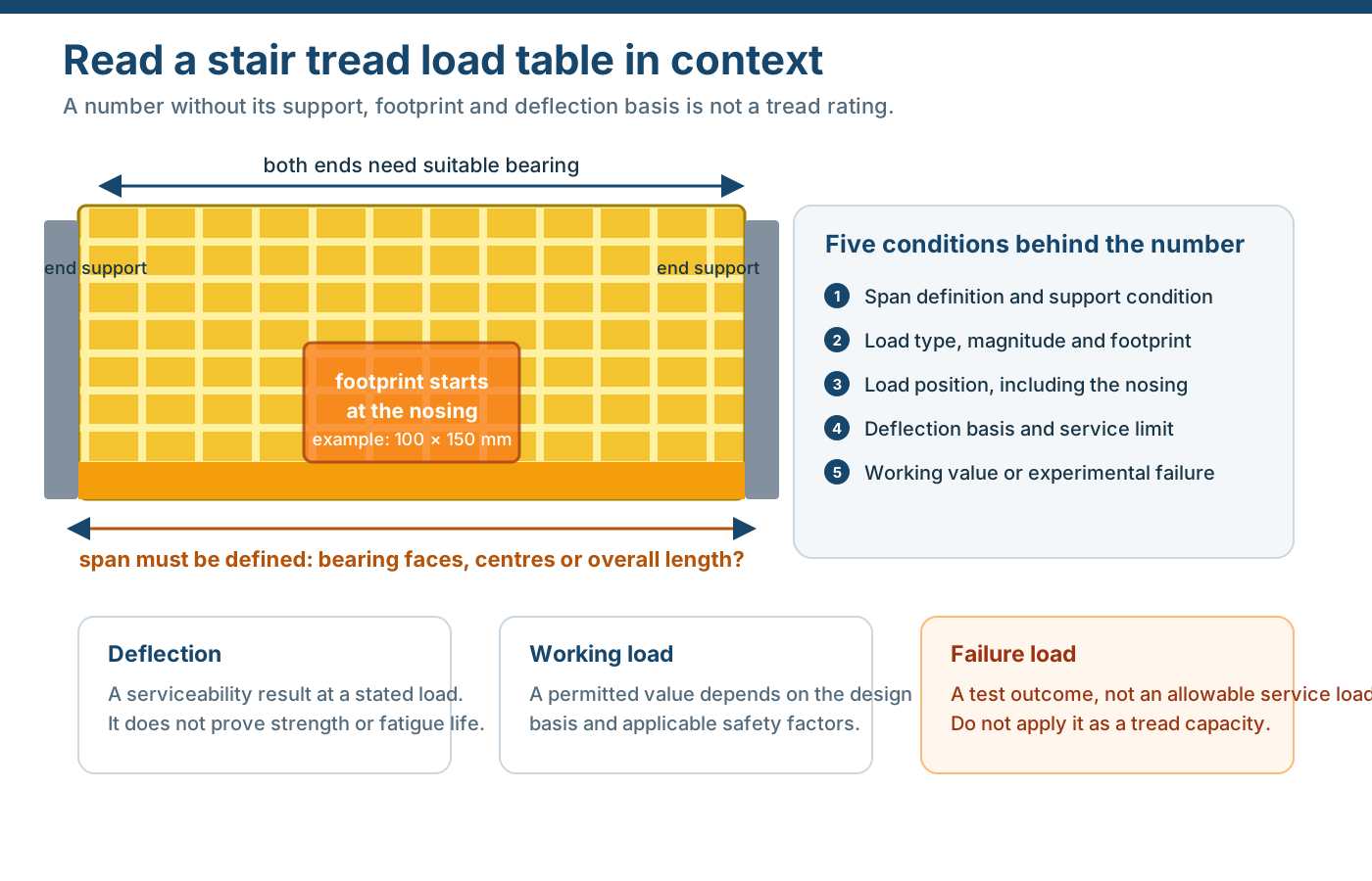
Use Load Evidence for the Actual Tread Condition
A pultruded profile does not carry one universal stair rating. The load path depends on the full profile row, span, end support, load footprint, load position and deflection limit.
For a stair, the critical load may sit near the nosing rather than at the middle of the tread. A concentrated foot load, maintenance equipment, impact against the front edge and repeated traffic can produce different conditions. The load table must state which case it covers.
Do not treat a maximum experimental load as a working load, and do not transfer a platform-panel row to a tread without matching the support and load position. If the project provides a design load and deflection limit, keep those inputs with the tread mark.
Carry Cut Ends, Edge Treatment and Piece Marks Through Fabrication
Pultruded tread fabrication may include cutting to walking depth, forming end details, drilling or slotting for the carrier, edge treatment and piece marking.
The release drawing should identify:
- the finished width and walking depth;
- square or angled ends and the controlling datum;
- which cut faces require resin edge sealing;
- the nosing attachment or joint face;
- hole and slot positions measured from the same datum;
- the tread mark and stair or flight identity;
- any protection required for the surface during packing.
A clean cut does not restore an interrupted bearing bar or create a nosing. Use the cut-end inspection guide when an end, opening or fixing interrupts the assembly.
A Practical Shop-Check Sequence
Before releasing a pultruded tread:
- Match the drawing revision, stair ID and tread mark.
- Confirm the profile, bearing-bar direction and top face.
- Measure the finished span and walking depth from the agreed datum.
- Check both bar-end conditions and the carrier interface.
- Confirm the nosing construction, projection and surface.
- Verify fixing positions and access against the stair detail.
- Inspect cut faces and apply the agreed edge treatment.
- Keep the piece mark and product identity through packing.
The useful unit is the complete tread, not the area of the original panel it came from.
The nosing and end-detail guide expands the front-edge and carrier details into a three-view quotation drawing. To compare pultruded and molded structures under the same stair duty, use molded vs pultruded stair treads.
The Pultruded Tread Rule
Start with the actual stair span and both end supports. Set the bearing-bar direction. Define the walking depth and nosing as real parts of the assembly. Check the carrier and fixing separately from bearing. Match load evidence to the same condition. Release the finished tread with an identity that survives packing.
That sequence keeps a pultruded stair tread from becoming an attractive piece of grating that does not fit the stair.
Review sequence
From the Stair Frame to a Released Pultruded Tread
Resolve support and direction before load comparison, fabrication and packing.
Measure the stringer or carrier faces and record the clear span and available bearing at both ends.
Show the main bearing bars running toward the two end supports; do not substitute cross rods.
Locate the front nosing and rear edge from a stated datum and show any projection beyond the support.
Identify whether it is integral or added and show its profile, attachment, projection and surface.
Show the seat, elevation, bolt access and how the tread is restrained.
Confirm the section, span, load position, support and deflection limit covered by the available data.
Check the cut ends, edge treatment, fixing positions, piece mark and packing before dispatch.
Release boundary
What Must Match Before the Tread Is Made
The tread, support, nosing, load condition and piece identity must belong to one revision.

One stair geometry
The tread length is measured between the actual end-support faces, not inferred from a stock panel.
One bar direction
The drawing shows which direction the pultruded bearing bars must travel.
One nosing assembly
The integral or added nosing and its attachment are named rather than implied by colour alone.
One carrier-and-fixing detail
End bearing and restraint are separately detailed.
One load condition
Available evidence is tied to the section, support, load position and deflection limit.
One finished-piece identity
The tread mark follows fabrication, edge treatment, inspection and packing.
RFQ checklist
What to Send With a Pultruded Tread Inquiry
A stair drawing and tread schedule remove most of the ambiguity.
- Stair elevation and plan — Stair angle, rise, going, clear width, stringer spacing and tread locations.
- Tread schedule — One mark per unique tread, with quantity, finished width and walking depth.
- Pultruded product row — I, T or WT family, depth, pitch, resin, surface and colour.
- End-support detail — Carrier plate, angle or channel, bearing width, elevation and fixing access at both ends.
- Nosing detail — Integral or added construction, profile, projection, attachment, colour and grip surface.
- Open-area and drainage requirement — Expected water, debris, footwear, small objects and cleaning method at the stair location.
- Load and deflection — Governing load, position, duration and deflection limit for the stair tread.
- Fixing and handling — Clip or bolt arrangement, material, removal requirement, piece weight and lifting route.
- Acceptance and packing — Edge treatment, marking, inspection record, document scope and package protection.
Request a review
Send the Stair Drawing or Tread Detail
Show the span, carrier, nosing and fixing location, then identify what remains unknown.
- The stair span and both end supports are reviewed
- Bearing-bar direction and nosing are shown together
- Carrier, fixing, load evidence and packing stay visible
Pultruded Fiberglass Stair Tread Questions
What is a pultruded fiberglass stair tread?
Can any pultruded grating panel be cut into a stair tread?
Can pultruded stair treads be cut from a longer grating run?
Does open area matter on a stair tread?
Which direction should bearing bars run on a stair tread?
What is the difference between stair width and tread depth?
What does an integral nosing mean?
Can a contrasting square profile be used as the nosing?
Can clips replace carrier plates or stair brackets?
How is the load capacity of a pultruded stair tread established?
Should the tread be made before the stair is measured?
What should be checked before a pultruded tread is packed?
This content was prepared and reviewed by Dengtai Industry’s technical and production team using the project conditions, available product data and applicable documents. Limits that require design, testing or approval are identified in the content. Content last checked: