Pultruded grating fixing guide
Pultruded Grating Clip Fit: Bars, Cross-Rods and Supports
Position the clip from the support layout, not from the middle of the panel. Match the panel height, bearing-bar geometry, jaw, support section, material and installation access before the fixing is released.
Prepared by
Dengtai Industry
Published
·
Reviewed

Clip positions follow support, movement and edge conditions in the walkway layout. Photo: Dengtai Industry.
Fixing terms
Clip, Connector, Support and Bearing
Four different functions that are often confused when a panel is installed.
- Hold-down clip
- A small fixing that restrains a grating panel against movement or uplift at a support or edge. It does not replace the structural bearing surface.
- Panel connector
- A fixing used at the boundary between two panels to limit relative movement or a local step. It does not turn the joint into a support or increase the allowable span.
- Fixing zone
- The location on the panel and support where restraint is required. It is taken from the support layout and fixing detail, not from a generic number of clips per panel.
- Bearing bar
- The continuous pultruded bar that carries the principal load toward the supports. A hold-down clip should engage the structural geometry shown on the approved fixing detail.
- Cross rod
- A transverse member that connects and stabilizes the bearing bars. Its visible position does not make it an alternative bearing support.
- Jaw fit
- The ability of the clip to seat on the actual bar geometry while reaching the bolt and support. Panel height alone does not establish jaw fit or installation access.
- Fixed restraint
- A fixing detail that prevents movement in the directions defined by the project. It must not introduce an unplanned clamp that conflicts with thermal expansion, removable access or the movement assumed by the design.
- Movement-accommodating fixing
- A fixing arrangement that retains the panel while allowing the specified relative movement. Whether movement is allowed, and in which direction, comes from the project fixing detail rather than a universal clip rule.
Function comparison
What M, L and C Fixings Normally Do
Use the letter as an entry point, then confirm the actual geometry and ordered panel.
Swipe horizontally to view all columns.
| Fixing condition | What it normally does | What it does not establish |
|---|---|---|
| M-style hold-down | Usually spans adjacent bars to retain the panel at a support. | Jaw fit, bolt reach, support capacity or a universal span increase. |
| L-style hold-down | Usually presses on one bar at a lighter fixing position. | Equivalence to M-style restraint or suitability for every pull-out condition. |
| C-style panel connector | Usually controls an edge joint or local panel-to-panel movement. | A bearing support beneath the joint or added panel capacity. |
| Midspan clip | May restrain local movement where the approved detail requires it. | A shorter structural span or a new bearing point. |
| Cross-rod-only contact | A cross rod may be part of the visible assembly near a fixing. | A valid hold-down path unless the approved fixing detail establishes it. |
| Fixed connection | Restrains the panel in the directions required by the fixing detail. | Permission for thermal movement or easy removal without a separate release procedure. |
| Movement-accommodating detail | Keeps the panel captured while allowing defined relative movement. | A loose, incomplete or unverified fixing that can let the panel lift or leave its bearing seat. |
Restraint review
When a Pultruded Grating Panel Needs Explicit Fixing
Fixing demand usually starts at support lines, edges and moveable panels.
Specify this if…
- The panel may be lifted by wind, wash-down or equipment movement.
- The panel is removable for inspection or maintenance and must return to the same position.
- Panels meet at an edge where relative movement or a local step must be controlled.
- The support section or site access requires a particular top-down or side-fixing arrangement.
- The specification already names a fixing type and the actual jaw and support fit need confirmation.
Look elsewhere if…
- A clip is being used to increase the allowable panel span.
- A clip is expected to provide bearing under unsupported bars.
- The panel height is the only information available.
- One universal fixing count is being copied onto a different support layout.
- The installation depends on a torque, bolt grade or anchor capacity not confirmed for the order.
Fixing interface
Eight Fields for a Pultruded Clip Record
Connect the panel, jaw, support, installation access and required restraint.
Swipe horizontally to view all columns.
| Interface field | What to record | Why it matters |
|---|---|---|
| Panel configuration | I/T/WT profile, depth, pitch, top width and surface. | The gripper must seat on the actual ordered bar and panel elevation. |
| Fixing position | Support line, panel edge, joint, opening perimeter or moveable edge. | Fixing demand changes with location; a midspan clamp is not a bearing point. |
| Support geometry | Angle, channel, flat bar, rail, beam flange or concrete kerb, with thickness. | Steel needs a stable clamping path; concrete needs a separately specified anchor system. |
| Bolt and tool access | Installer works from above or below; required length and available headroom. | A clip that cannot be reached cannot be fitted or maintained correctly. |
| Material | Galvanized or stainless direction, with the required grade and coating. | Fastener material must suit exposure and contact with the support. |
| Movement | Restraint, thermal movement, removable panels and reinstatement procedure. | Overfixing can conflict with movement; loose fixing can leave the panel unseated. |
| Quantity and layout | Positions from the support and fixing drawing, not a universal clip count. | Load path, edges and local fixings determine the required restraint. |
| Release record | Clip type, material, hardware, quantity and drawing revision. | Procurement and installation must match one identified assembly. |
A pultruded grating clip should be positioned where the panel meets a support, edge or joint that requires restraint. Match the clip to the actual I, T or WT bearing-bar geometry, panel height, jaw clearance, support section and installation access.
Do not choose the position from the middle of the panel. A clip does not shorten the span, add bearing under an unsupported bar or turn a cross rod into a support member.

Start With Fixing Location
Mark the support lines on the panel layout. Then identify the places where the panel must be restrained:
- along a support;
- at an exposed edge;
- at a panel-to-panel joint;
- around a removable opening;
- near an edge where uplift or movement is possible;
- beside a lifting or access point.
The fixing schedule should show the locations. A parts count without a layout is not enough to install the order.
“At the support” matters because bearing and retention are different jobs. The support carries the panel. The clip keeps the panel in place and restrains the movement identified by the installation design.
Match the Fixing Method to the Support
The clip cannot be selected without the support beneath it. The fixing path changes with the type of structure:
| Support condition | Information the fixing review needs |
|---|---|
| Steel angle, channel or beam flange | Section and thickness, accessible top or side face, bolt path, edge distance, pre-drilled condition and whether the clip can seat without distorting the steel |
| Concrete kerb or base | Anchor type and substrate capacity, embedment, edge distance, drilled-hole condition, corrosion protection and any waterproofing detail |
| Rail, purlin or formed frame | Actual profile and wall thickness, open or closed section, clamping access, local distortion risk and the continuous support line |
| Existing galvanized frame | Measured section, coating condition, hole condition, support soundness and compatibility of clip and bolt materials |
Steel and concrete do not share one default anchor. A concrete fixing may need a mechanical or chemical anchor selected for the base and load; a steel angle or flange is commonly clamped or through-bolted where the detail allows. Those are different interfaces, and the project must confirm the fastener, capacity and installation instruction.
Send the support section or a marked photograph with a scale and the fixing position. The clip height may look correct while the bolt cannot reach the support or the tool cannot access the head.
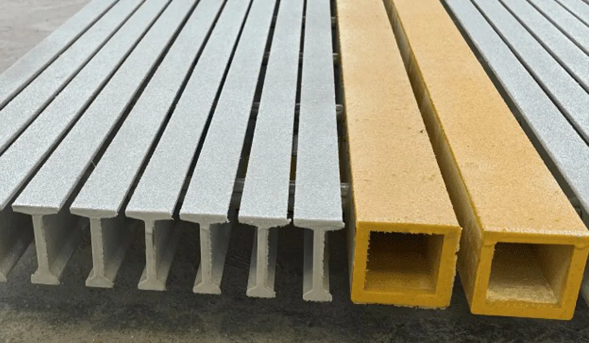
Do Not Confuse Cross Rods With Bearing Bars
Bearing bars run toward the supports and carry the principal load. Cross rods run across them and stabilize the assembly.
A cross rod may be visible above the support and may even touch the frame, but the cut and fixing detail still has to establish how the panel is restrained. The bearing-direction guide and cut-end guide explain the related geometry.
Before accepting a fixing position, confirm:
- the clip is engaging the intended structural element;
- the fixing point reaches the support;
- the jaw is not held off by a cross rod or surface irregularity;
- the bolt has a stable path into the support;
- the location does not rely on an unverified cross-rod load path.
Match the Panel, Not Just the Letter
Our factory can supply M, L and C fixing families with heights matched to the grating panel. The actual jaw and panel relationship are checked for the order.
The familiar forms are:
| Clip form | Typical function | Check before use |
|---|---|---|
| M-style | Usually spans adjacent bars and holds the panel to a support | Panel height, bar spacing, jaw fit, support and bolt access |
| L-style | Usually presses on one bar for a lighter fixing position | Single-bar contact, bending or pull-out risk and support access |
| C-style | Usually connects adjacent panel edges to control the joint | Both edge geometries, joint support and whether the piece is removable |
The letters are not a universal strength ranking, and another supplier’s M clip may not fit our profile.
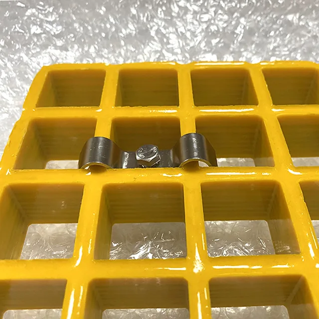
Check Height and Jaw Together
Height matching prevents a clip from pulling the panel out of shape. It does not prove that the jaw clears the actual top flange or that the bolt reaches the support.
Record:
- ordered panel depth;
- I, T or WT profile;
- bearing-bar top width;
- pitch and visible opening;
- surface thickness or grit presence;
- support section and flange thickness;
- bolt length and washer requirement;
- access from above, below or the side.
A clip with the right height but the wrong jaw still does not fit. A jaw that touches only the edge of a flange may not provide the intended seating.
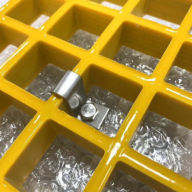
Treat Panel-to-Panel Connections Separately
A C-style connector may keep adjacent panel surfaces aligned or limit relative movement at a joint. It does not:
- create a support below the joint;
- increase allowable span;
- make two separately supported panels act as one continuous member;
- automatically replace an edge fixing to the structure.
Show the panel joint on the support layout. If the joint needs structural support or a controlled movement detail, that belongs to the project design and fixing drawing.
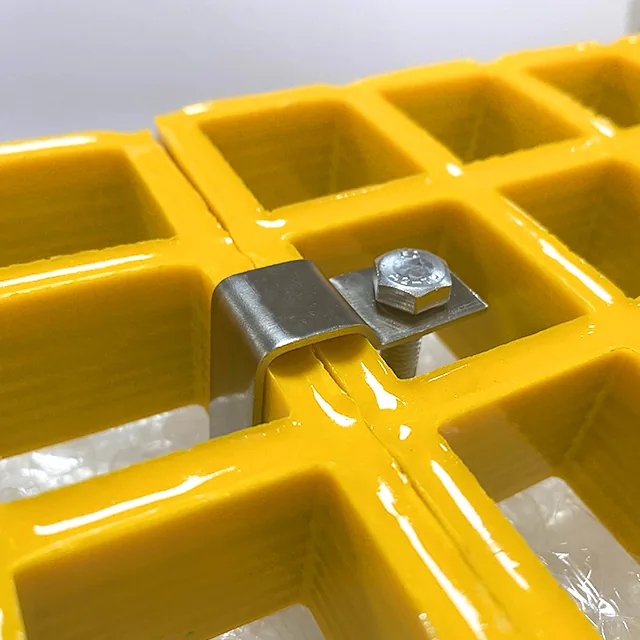
Build Quantity From the Layout
We do not publish one universal number of clips per pultruded panel. Quantity depends on:
- support lines crossed by the panel;
- size and aspect ratio of each piece;
- edge exposure and uplift condition;
- traffic, vibration and equipment movement;
- removable-panel and reinstatement needs;
- local fixing positions around openings and corners;
- project specification and installation documentation.
Prepare a fixing line for each unique piece. If the count changes when the panel is split, the quotation and drawing should change with it.

Decide What Is Fixed and What May Move
“Fixed” and “sliding” describe the intended movement behaviour of the fixing detail, not two clip sizes. A fully restrained clip prevents uplift and walking in the specified directions. A movement-accommodating detail keeps the panel captured while allowing the relative movement assumed by the design.
State the design intent for each panel or run:
- whether thermal expansion and contraction must be accommodated;
- which edges or joints are restrained and which may move;
- whether the panel is lifted for inspection or maintenance;
- whether one fixing must release before the others;
- how the reinstated panel returns to the same piece mark and bearing direction.
Do not create movement by leaving hardware loose, and do not remove all movement by tightening every clip without checking the detail. Either can change the condition the support and fixing design assumed. Long runs, mixed steel and concrete supports, temperature change and removable sections should be reviewed before the fixing schedule is released.
Choose the Material From Exposure and Specification
Galvanized and stainless steel clips are both made to order. The clip, bolt, washer and any anchor should be identified in the offer.
Confirm:
- indoor, outdoor, coastal or chemical exposure;
- cleaning method and frequency;
- support material and risk of galvanic interaction;
- required stainless grade or galvanizing standard;
- whether the same material is required for every fastener component.
The general clips guide explains the broader M/L/C scope, and the clip material guide separates the clip body from the bolt, nut, washer and support contact. The numbered layout guide keeps bearing-bar support points and panel joints in separate schedules.
Plan Removable Panels and Reinstatement
A removable panel needs more than a loose clip count. Give the piece:
- a unique mark;
- a bearing-direction mark;
- a fixing location record;
- a reinstatement check;
- enough fixing hardware that remains with the correct panel or package.
After maintenance, verify that the panel sits on the supports, follows the correct direction and is restrained at the approved points. Do not judge reinstatement by appearance alone.
Inspect the Installed Clip, Not Only the Part
The flat part in a photograph is not the finished fixing. After installation, check the complete interface:
- the correct clip family, material and hardware are fitted at the marked positions;
- the jaw seats on the intended pultruded bars without touching only a flange edge;
- bolt, nut, washer or anchor components are complete and accessible for later inspection;
- the panel remains in contact with its support faces and does not rock or bridge over a high point;
- the bar, resin and surface are not crushed, cracked, delaminated or visibly distorted;
- movement or restraint matches the approved fixed, sliding or removable detail;
- piece marks, direction marks and reinstatement records remain legible.
Record a deviation rather than tightening harder. Excess tightening can damage the bar or pull the panel off another bearing point. A panel that was already unsupported does not become supported because the clip is secure.
What We Need Before Quoting
Send:
- the exact pultruded panel and piece schedule;
- support section and fixing positions;
- clip family if already specified, or the required restraint function;
- access for bolts and tools;
- galvanized or stainless requirement;
- removable-panel and movement conditions;
- any project fixing standard, torque or inspection requirement.
Clips are quoted as a visible line and supplied with the grating order. Because the jaw and height are matched to the panel, clip-only orders are not shipped.
The Clip-Placement Rule
Place restraint where the support and fixing drawing requires it. Match the jaw to the ordered bearing-bar geometry and the bolt path to the support. Keep supports, connectors and fixings as separate functions.
The correct clip is the one that fits the complete interface and performs the required restraint without being represented as added span or bearing capacity.
Fixing sequence
From Support Drawing to an Approved Clip Schedule
Resolve location and fit before quantity or material is finalised.
Identify the support faces and the panel edges or joints that require restraint.
Confirm the exact I/T/WT profile, depth, pitch and top width.
Confirm the clip seats on the bar without forcing and has a sound path to the support.
Decide whether the fastener is fitted from above, below or the side, and confirm reach.
Agree galvanized or stainless scope and whether the panel will be lifted.
Confirm both bearing and clip contact before final tightening; the panel must not rock or bridge between high points.
Show clip family, hardware, quantity, positions and revision on the approved drawing.
Check hardware completeness, bar distortion, support contact, panel movement and reinstatement marks.
Installation boundary
What a Pultruded Grating Fixing Record Must Show
The fixing is traceable when its panel, support, hardware and positions are connected.

Support location
The clip is positioned where the panel meets the intended support, edge or joint.
Correct panel interface
The jaw and fixing height match the ordered pultruded profile and panel build.
Complete hardware
Bolt, washer, nut or required anchor are identified with material and length basis.
Correct restraint
The fixing restrains the panel without being presented as added strength or span capacity.
Material scope
Galvanized or stainless direction and any required grade are visible in the quotation.
Controlled reinstatement
Removable panels retain a position and fixing record so they return to the correct place.
Post-installation condition
The panel still bears on its supports, the bars are not crushed and the installed hardware is complete.
RFQ checklist
What to Send With a Pultruded Clip Question
Include the panel, support, fixing location, material and removal requirement.
- Panel configuration — Exact profile, depth, pitch, top width, surface and piece mark.
- Support drawing — Support type, section, flange or web access, positions and bearing faces.
- Fixing location — Where restraint is required, including edges, joints, openings and removable panels.
- Direction and top face — Bearing-bar direction and any location-sensitive top finish.
- Environment — Chemical exposure, cleaning, coastal or wet service and required fastener material.
- Support substrate — Steel section or concrete base, material thickness, predrilled or anchor condition, edge distance and access.
- Movement and removal — Thermal movement, expected lifting and reinstatement requirements.
- Hardware requirement — Bolt, nut, washer or anchor scope, with the support thickness and access direction.
- Acceptance — Required fit inspection, fixing record and any project torque or installation instruction.
- Post-installation check — What must be verified after tightening, including hardware, seating, deformation, movement and piece identity.
Request a review
Send Your Pultruded Grating Fixing Detail
Upload the support layout and identify where the panel must be restrained.
- Fixing positions linked to the support drawing
- Clip height, jaw and hardware checked together
- Clip line remains visible in the quote
Pultruded Grating Clip Questions
Where should pultruded grating clips be placed?
How many clips do I need per pultruded grating panel?
Is a cross rod strong enough to hold the clip?
Is panel height enough to choose the clip?
Are M, L and C clips interchangeable?
Does a panel-to-panel connector increase the allowable span?
Do clips add the bearing required under a bearing bar?
Can clips be supplied separately for an existing panel?
What determines galvanized versus stainless clips?
Can you give the exact torque or fixing count?
Does a steel support and a concrete support use the same anchor?
How do I know whether the clip should allow thermal movement?
What should be checked after the clips are tightened?
How should a removable panel be reinstated?
This content was prepared and reviewed by Dengtai Industry’s technical and production team using the project conditions, available product data and applicable documents. Limits that require design, testing or approval are identified in the content. Content last checked: