FRP platform edge review
FRP Platform Edges: Reducing Trip and Transition Risks
Measure the grating and adjacent floor from one finished-surface datum, then define who uses the route, how the edge is closed, where the panel is supported and fixed, and which party owns the civil, warning and fall-protection interfaces.
Prepared by
Dengtai Industry
Published
·
Reviewed

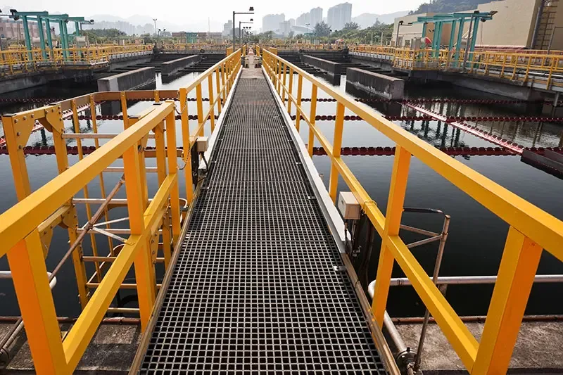
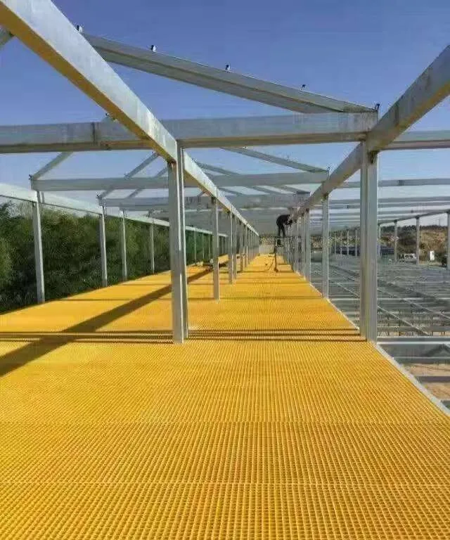
A continuous platform still has to resolve the approach, perimeter and changes of level. Photo: Dengtai Industry.
Start With the Actual Boundary
An FRP platform edge is not only the last bar of the last panel. It is the boundary between the grating and whatever comes next: a concrete floor, steel plate, another grating, a curb, a wall, an opening or a change in level.
The user experiences the result through the top surface. The project still has to control the supported edge below it. A boundary that appears neat from above may have an unsupported panel edge, a frame that stops short, a shadow gap, a fixing head above the floor or a guard connection that was never coordinated.
This page reviews the interface a buyer can describe and the factory can contribute to. It does not approve the civil floor, frame design, guardrail, fall protection or building accessibility as part of a grating panel name.

Measure From One Finished Datum
Do not compare a platform drawing elevation with a generic concrete-level note. Define a common datum and measure both surfaces in the installed condition.
Record:
- the platform top surface at the approach;
- the adjacent floor or structure;
- both sides of every joint;
- the perimeter along its length;
- the top of any trim, ramp or frame; and
- the support or bearing beneath each reading.
One “flush” measurement at one corner is not enough. A panel can be level locally and rise or fall along the edge. A floor can be flat but not coplanar with the platform. A transition piece can be correct at its centre but create a high fixing or open gap at each end.
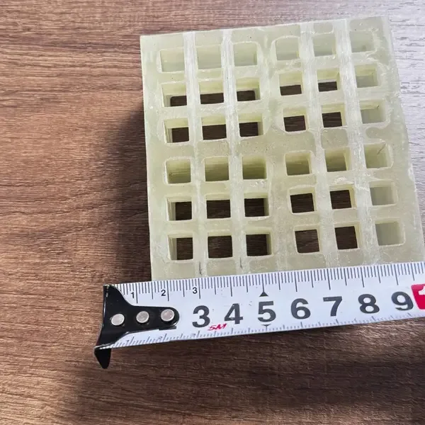
For an accessible route, use the relevant project criteria and measure the complete route. The ADA route guide explains why joints, changes in level and the installed surface belong to one review. This page does not turn a local product dimension into a compliance statement.
Do Not Read One Level as a Level Route
The edge can be flush at one point and still create a difficult route.
Check the longitudinal change along the direction of travel and the crossfall across the platform. A panel that drops gradually toward the perimeter may create a larger finishing difference at the trim than the nominal support drawing suggests.
For wheeled traffic, a local bump and a long slope behave differently. The local edge decides whether the wheel catches, while the long slope changes effort, traction and the way the carried load shifts. A foot route may tolerate a small irregularity that a trolley repeatedly impacts at speed.
Record the route direction and the level readings on the same plan. If a joint runs across the walking direction, evaluate both sides of that joint. If it runs along the direction of travel, check whether one side has been installed high enough to form a continuous trip line.
The grating layout and the finished floor may have been designed by different parties. The visual result still combines both surfaces at the boundary, so the measurement must represent the installed assembly rather than the nominal drawings separately.
Record Who Meets the Edge
Foot traffic is the minimum case, not the only one.
Ask whether the edge will see:
- boots, bare feet or other footwear;
- pallet trucks and hand carts;
- trolley or wheelchair wheels;
- maintenance tools and carried equipment;
- temporary storage during service; or
- emergency or assisted evacuation.
A small wheel may stop at a joint that a boot crosses easily. A ramp that helps a cart can intrude into a walking route. A covered grating transition may present a different surface from the adjacent concrete.
The route direction also matters. Slopes, joints and elongated openings should be considered in the direction people actually move. Mark the approach side and any turn or crossing on the edge drawing.
Identify the Edge Closure Type
There is no universal “edge strip” that finishes every platform.
Possible closures include:
- the panel bearing on a frame with a defined visible edge;
- an edge trim or angle;
- a shaped ramp where the level change and route call for one;
- a curb, upstand or fixed barrier;
- a supported open edge with guarding or access restriction; or
- a removable transition piece with its own release and reinstatement method.
Each approach has a different support and fixing problem. A trim does not become structural because it is bolted to the panel. A ramp needs a supported base and a geometry suited to the users. A guard needs its own design and anchorage.
The Fibergrate edge-ramp product shows that a manufacturer may treat a 90-degree platform drop as a separate accessory with dimensions, surface and fixing. That is a useful reference for the questions to ask, not evidence that the same ramp fits another product or project.

Ramp Geometry Must Follow the User
A ramp is not defined by its colour or its length alone.
For a ramp or shaped transition, the project should define:
- the high and low finished surfaces;
- rise and run;
- transition length and width;
- edge alignment with the walking route;
- the surface and edge visibility;
- how the ramp is supported; and
- how it is fixed against movement.
The geometry has to fit the intended users. A short ramp added for a small step may not suit a cart with a long wheelbase. A long ramp can project into an access aisle or conflict with a door, guard post or drain. A grit surface can help the foot contact but does not correct an abrupt beginning or end to the ramp.
Project accessibility requirements may impose specific limits on level changes and slopes. Those requirements apply to the installed route and its use, not to one generic FRP accessory. The Access Board ground-surface guidance explains that broader context.
Where a ramp is proposed, ask the supplier to state exactly what is being supplied: a shaped FRP piece, a trim, a complete ramp assembly or only the grating base. The quotation should not leave the buyer to infer which part creates the walking slope.
Turn the Ramp Into a Buildable Accessory
A ramp product photo does not define what will be fabricated. Build the line item from six connected decisions:
- Match the grating and ramp section. State the exact panel type and depth, the ramp profile, and how the two edges meet. A ramp offered for one panel construction is not evidence that it fits another.
- Define the walking face. Record the specified surface, colour and edge visibility. Grit can improve contact, but it does not correct an abrupt start, a long slope or a raised fixing.
- Resolve length and corners. Show delivered lengths, field-cut limits, direction, joints and any miters. A perimeter with several corners is not one straight accessory repeated.
- Control cut ends. State whether ends are cut and sealed in the factory or on site, and who completes the treatment. An exposed field cut must fit the approved edge condition.
- Set the fixing layout. The traffic class, support material, clip or anchor, edge distance and installation access belong on the same drawing. Spacing from a generic ramp detail should not be copied to a different construction.
- Name the supply boundary. The quotation should distinguish the ramp piece, hold-downs, screws, anchors, sealant and installation from work supplied by others.
Fibergrate publishes an edge-ramp installation sheet that treats the ramp as a product with depth choices, a walking surface, fixed or fabricated length, miter connections, cut-end sealing and a fixing layout. Those fields show the right level of detail to request. Its dimensions and clip schedule remain specific to that manufacturer’s product and are not a cross-reference to our range.
Resolve the Support Below the Transition
The edge closure should have a load path into the platform frame or adjacent structure. “The concrete is directly underneath” is not enough if the panel bears on a local high point, a narrow ledge or a frame that was set too low.
Show:
- which edge bars or bearing bars engage the support;
- the bearing width;
- the frame or floor interface;
- how the trim or ramp is fixed;
- the access required to reach the fastener; and
- whether the adjacent floor is cast first, second or adjusted afterward.
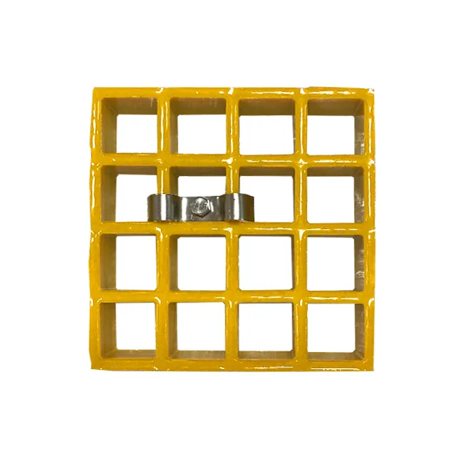
A hold-down clip can restrain the panel, but it cannot fill a gap, create a transition surface or support an unsupported edge. The panel joint and support guide explains why support routing and visible edge connectors must remain separate.
Coordinate the Construction Sequence
The finished interface depends on the order in which the frame, supporting structure, grating and adjacent floor are completed.
If the concrete floor is placed after the platform is set, the final finish level may rise or fall from the structural slab level. If the frame is adjusted after the grating is cut, an edge that was fabricated with a defined bearing may no longer sit correctly. If temporary packers are installed for construction access, they should be removed or replaced under the approved detail before handover.
The drawing should identify:
- which structure is surveyed first;
- which party sets the final frame or floor level;
- when the panel dimensions become fixed;
- which temporary supports must not remain;
- who checks the completed interface; and
- what happens if the measured field level differs from the drawing.
This is a coordination sequence, not a claim that the grating factory can control every trade. It prevents a completed panel from being cut to a frame that is later moved or packed to match a floor that is not finished.
Keep Surface and Structure as Separate Choices
A grit or concave surface changes how the walking surface behaves. It does not set the finished level or close the perimeter.
A covered grating can make the top appear solid, but its base support, cover thickness, perimeter joint and water path still have to agree. A pultruded grating needs its bearing-bar direction preserved at the edge. A molded panel carries load through its grid but still needs a defined bearing contact.
Where the route sees oil, water, debris or frequent cleaning, read the surface and treatment guide together with the transition detail. A rough or gritted surface should not be asked to compensate for a badly shaped step.
Define Warning and Guarding Scope
Warning markings can draw attention to a change in level, but they do not correct it. Guardrails, barriers, gates or opening protection can control access to an exposed edge, but they belong to the system design.
The grating quotation should show any agreed marking, trim or fixing that is actually supplied. It should not imply that a standard panel edge is an engineered barrier.
Where a guardrail post lands at the same platform boundary, use the guardrail post opening guide to coordinate the post base, structural support and grating clearance without treating the panel as the anchorage.
If the platform edge is also an opening edge, coordinate the removable panel guide and the project’s open-hole procedure. The factory can identify the panel and supplied hardware; the site still controls the temporary opening condition.
Inspect the Approach, the Edge and the Route
An inspection that looks only at the perimeter misses the conditions that create the hazard.
Walk the route from the adjacent floor toward the platform, then along the edge in both directions. Check whether the eye sees the edge before a foot or wheel meets it. Look for a joint line that disappears behind the panel, a trim that catches a shoe and a change in surface texture that reads as a step.
For a wheel route, roll or measure the actual wheel across the transition more than once. A wheel can pass the centre of a ramp and catch at one side where the frame is high. For a foot route, inspect the full edge for loose trim, protruding fasteners, grit loss and debris that changes the apparent level.
Record the condition with photographs from the approach, directly above the interface and below the bearing edge. Add a scale where geometry is the subject. The maintenance record should retain the original edge ID so a later change can be compared with the approved finish.
Decide What Belongs to the Factory
Our factory can review the offered panel, the cut edge, piece marks and any agreed trim or edge piece within the written scope. We can flag a missing support, inaccessible fixing or conflicting level detail before fabrication.
We cannot approve:
- the adjacent concrete or structural frame;
- fall protection, guarding or anchorage;
- a complete accessibility route; or
- a site installation sequence that changes the support or finished level.
Those items should be named on the same edge drawing with their owners.
Inspect the Finished Transition
At handover, check the edge along its length:
- the platform and adjacent surface from one datum;
- joint or perimeter gap;
- edge closure and fixing;
- bearing contact;
- surface texture and cleaning condition;
- warning or guarding interface;
- route clearance; and
- any open item.
Photograph the edge from the approach, along the platform and below the support. A single top-down phone image cannot show both the walking level and the bearing condition.
Our Factory View
We can quote a panel edge only when the adjacent surface, support and closure are defined. The factory can fabricate agreed cuts, edge treatment and piece marks. It can supply a compatible fixing system when included. It cannot infer a concrete finish, create a structural frame or certify a guard from a panel drawing.
The owner of each boundary should be visible. That is more useful than a generic note saying “site to finish flush.”
Edge review
Send the Boundary Plan and Section
Include the adjacent floor, route users, support, fixing and guarding scope.
- Mark the adjacent surface and owner
- Measure from one finished datum
- Separate guarding from grating
Transition conditions
Which FRP Platform Edge Detail Must Be Measured?
Start with the adjacent construction, users and actual level rather than a generic ramp.
| Edge condition | What must be defined | What is not proof |
|---|---|---|
| Platform to concrete floor | Finished levels, joint width, edge closure, anchor or frame | Two drawings showing the same nominal elevation |
| Platform to steel grating or plate | Support transition, material interface, fixings and top-surface alignment | Similar panel colours |
| Small local step | Actual step, route direction, footwear and approved detail | A generic ramp note without rise or run |
| Open platform edge | Edge support, trim, access restriction and system guarding responsibility | A hold-down clip treated as fall protection |
| Carts or trolley traffic | Wheel size, load, direction and edge/wheel contact | Pedestrian-only slip data |
| Removable transition | Lift method, restraint, reinstatement and open-state protection | “Loose panel” called removable |
Edge register
Platform Edge Height and Closure Check Map
These fields connect the finished level, route, closure, support, fixing and responsible party.
| Edge record | Required value | Why it matters |
|---|---|---|
| Edge ID | Unique boundary ID and drawing revision | Keeps the same transition visible from layout to inspection |
| Adjacent surface | Concrete, steel, another grating, wall, curb or opening | Identifies the actual interface owner |
| Surface levels | Measured values at multiple points from one datum | Reveals step, slope or twist |
| Route users | Foot traffic, carts, wheels, maintenance or emergency use | Changes closure geometry and exposure |
| Edge closure | Frame, trim, ramp, curb, open edge or removable strip | Defines the physical termination |
| Ramp build | Matched panel depth, rise, run, width, surface, colour and traffic class | A named accessory does not prove the profile fits the project |
| Length and corners | Delivered lengths, joints, direction and miter locations | Corners and transitions must be fabricable |
| Support | Bearing surface and load path beneath the edge | Prevents the transition from carrying the panel by accident |
| Fixing | Hold-down, fastener, anchor and access | Separates panel restraint from civil or guard attachment |
| Cut-end treatment | Factory or field-cut method, sealing and responsible party | A clean cut is not a finished edge |
| Gap and warning | Joint or clearance and any marking requirement | Connects visible hazard control to geometry |
| Guard or opening protection | Required system and responsible party | A grating edge detail cannot certify fall protection |
| Release | Installed inspection, photographs and open items | Confirms the actual boundary condition |
Edge readiness
When a Platform Edge Is Ready to Quote
Release the edge only when its level, users, support and system boundaries are reproducible.
Specify this if…
- The adjacent finished surface and datum are identified.
- Actual levels are measured along the route, not only at one corner.
- Foot, cart and maintenance use are stated.
- Edge closure, support, fixing and gap are shown.
- The ramp depth, surface, length, corners, cut-end seal and fixing scope are stated.
- Screws, anchors and other separately supplied hardware have a named provider.
- The civil, guarding and opening-protection scope is assigned.
- A removable transition has a release and reinstatement record.
- The installed step and joint can be inspected.
Look elsewhere if…
- The transition is described only as “make flush.”
- A ramp or trim is requested without rise, run, width and fixing.
- The panel edge is assumed supported because it appears close to concrete.
- A clip is expected to provide fall protection.
- “Ramp” is quoted without length, corner, edge-sealing or fixing details.
- Wheel traffic is ignored because the route is normally pedestrian.
- Civil level and grating scope are left for site interpretation.
- No one controls the temporary condition during installation.
RFQ checklist
What to Send With an FRP Platform Edge Drawing
The listed records make the level, route and interface review usable.
- Edge ID — Unique boundary reference, plan location and drawing revision.
- Adjacent construction — Material, finish and owner of the concrete, steel, wall, curb or other surface.
- Level readings — Platform and adjacent values at multiple points from one datum.
- Route users — Footwear, trolleys, carts, wheels, maintenance loads and escape use.
- Closure detail — Frame, trim, ramp, curb, open edge or removable strip with dimensions.
- Ramp build — Matched panel depth, rise, run, width, surface, colour and traffic class.
- Corners and cut ends — Miter or joint locations, delivered lengths, field cuts and sealing method.
- Support — Bearing surface and structural carrier beneath the edge closure.
- Fixing — Clip, fastener, anchor, material and installation access.
- Gap and warning — Joint or clearance, edge marking and any tactile requirement.
- Guarding — Guard, barrier, gate or opening protection required by the project.
- Temporary condition — Open edge or incomplete transition control during installation.
- Interface owner — Grating, frame, civil, guard and final acceptance responsibilities.
- Inspection — Installed step, gap, support, fixing, marking, photographs and open items.
FRP Platform Edge Transition Questions
What is the most common cause of an FRP platform edge trip?
Can a grating panel with the right thickness make the edge flush?
When is an edge ramp appropriate?
What must a grating edge-ramp quotation include?
Who supplies the edge-ramp screws or anchors?
Is edge trim required on every FRP platform?
Does a hold-down clip make the platform edge safe?
How should accessible transitions be handled?
What changes when carts or trolleys use the route?
Can the transition be removable?
Who owns the adjacent concrete and guardrail?
What should be sent for an edge review?
Final release rule
Release the Edge Only When Level and Ownership Agree
A finished transition belongs to the complete route, not to one panel edge.
- Final release rule — Release the edge only when the actual level, route users, edge closure, support, fixing, warning and guarding responsibilities describe one approved condition.
- Keep system scope visible — The grating and agreed edge component are product supply. Civil structure, frame design, guardrails, fall protection and the accessible route remain separate scopes.
- Edge-ramp reference — Fibergrate treats a platform-to-floor drop as a separate edge ramp with defined panel depth, surface, length, cut ends and fixing. Open the Fibergrate edge-ramp page
- Edge-ramp execution reference — The peer installation sheet shows the level of product, cut-end, miter and fixing information a buildable ramp record should carry. Open the Fibergrate installation sheet
- Accessible ground-surface reference — The U.S. Access Board explains why level changes, joints and the complete route belong to the accessible-surface review. Open the Access Board ground-surface guide
- Walking-working surface reference — OSHA 1910.22 covers the general duty to keep walking-working surfaces clean, safe and inspected. Open OSHA 1910.22
This content was prepared and reviewed by Dengtai Industry’s technical and production team using the project conditions, available product data and applicable documents. Limits that require design, testing or approval are identified in the content. Content last checked: