CANDIDATE A
First molded row
- Depth: 25, 30, 38 or 50 mm
- Mesh: both directions stated
- Support and clear span: same drawing
- Load and deflection: same project case
- Evidence: exact molded row
FRP grating depth review
Compare depth only after the construction, support, clear span, load, deflection and panel handling are on the same drawing. A 25, 38 or 50 mm label can identify several different molded rows or pultruded bar series.
Prepared by
Dengtai Industry
Published
·
Reviewed

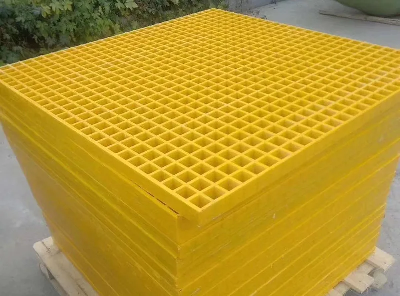
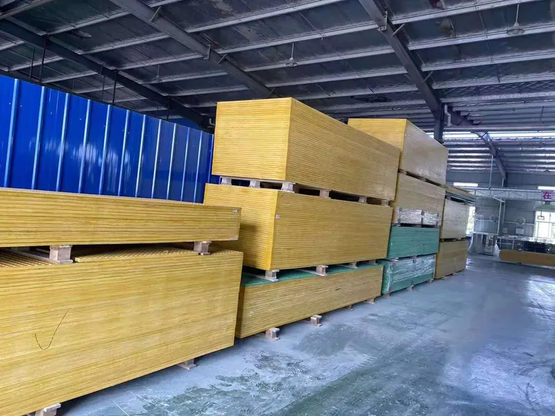
The depth label is only the first field. The deck must also fit the frame, mesh, load and handling plan. Photo: Dengtai Industry.
FRP grating thickness is a product dimension, not a performance class. A quotation for “25 mm,” “38 mm” or “50 mm” does not yet identify the mesh, bearing-bar series, resin, surface, support condition or load evidence. Two panels with the same nominal depth can differ in mass, load path and suitability.
This guide is a screening method for buyers comparing the common 25, 38 and 50 mm options. It includes our 30 mm molded row because it is part of the same selection decision, then shows why molded and pultruded depth should never be treated as interchangeable.
The practical sequence is:
If the open question is limited to our molded rows, use the detailed molded grating depth worksheet after this page. This article is intentionally broader because a buyer searching for FRP grating thickness may also need to compare a pultruded alternative.
This guide is prepared and reviewed by Dengtai Industry’s FRP grating technical and production team. Any offered depth remains a candidate until the current product row, support condition and applicable evidence are confirmed.

The word thickness is used in catalogs for several related measurements. Start by asking what the dimension represents.
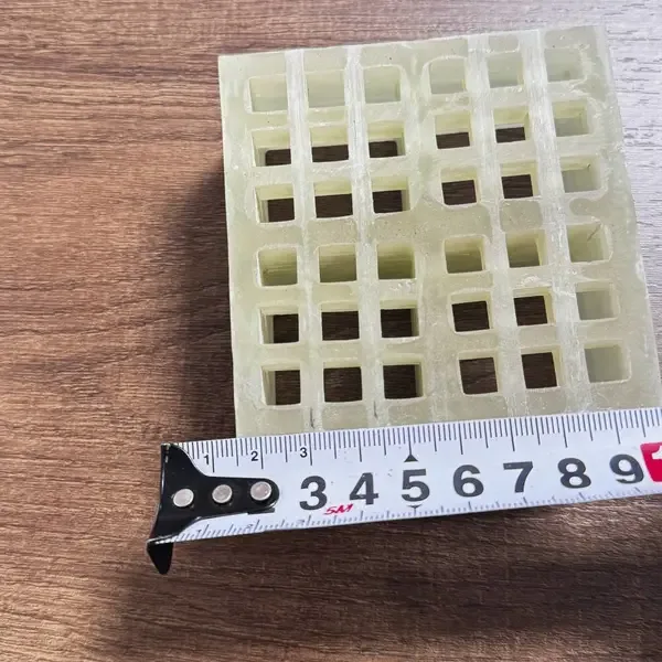
For an open molded grating, the nominal depth is commonly the overall panel section from the top of the molded grid to the bottom. It belongs to a particular mold and mesh. A 38 mm molded panel with 38 x 38 mm mesh is not the same product as a 38 mm panel with another bar geometry or a fine upper mesh.
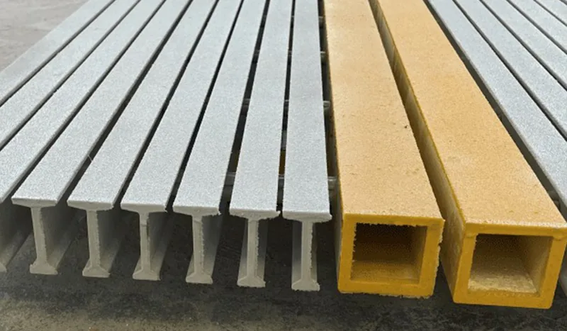
For pultruded grating, the quoted depth is usually the bearing-bar height. The same height can come with an I, T or WT profile and different top width, web geometry, pitch and open area. The bar direction carries the main span.
A covered grating may combine a base panel, interface layer and walking cover. The finished total height should not be called the base panel depth without explanation. The complete assembly also changes drainage, mass and load basis.
Grit or another raised finish can change appearance and slightly affect the finished envelope. The surface does not convert the base depth into a new structural grade.
Mass is a separate purchase and handling field. It is not an allowable load. A lighter panel is not automatically weaker, and a heavier panel is not automatically stronger. The construction and section properties determine how the load is carried.
Our current molded product record includes a 25 mm, 38 x 38 mm row at 12.5 kg/m² and a separate 25 mm, 40 x 40 mm tree-pit row at 10.5 kg/m² in 1220 x 4040 mm and 1000 x 4040 mm formats. The factory’s application record describes the tree configuration as generally not load-bearing, so it is not a general structural rating. See the dedicated FRP tree grate guide for that boundary.
A configured solar-walkway order used 25 mm molded grating with a 38 x 38 mm mesh, a grit surface and pieces cut to 400 x 2000 mm. That record confirms an available configuration; it does not establish suitability for another project.
The 30 mm, 38 x 38 mm row is listed at 16.5 kg/m². It is a common factory starting point for construction pedestrian access. “Starting point” matters. The actual clear span, equipment load, deflection limit, support and exposure still need a matching check.
The molded 38 mm, 38 x 38 mm row is listed at 19.5 kg/m². Our pultruded I38 range includes 40, 50 and 60 mm bar pitch at 23.0, 20.0 and 18.5 kg/m². The similar nominal depth does not make them equivalent. One is a molded grid; the other has directional bearing bars and a different assembly.
The 50 x 50 mm molded row is listed at 21.5 kg/m². It is a deeper standard row. A request for a 50 mm walkway still needs support and load information.
Our 25 x 50 mm heavy-duty row is listed at 45.0 kg/m², more than twice the nominal mass of the standard 50 mm row. It is a distinct product with a different mesh, panel mass and handling requirement. The phrase heavy duty does not replace project evidence.
The T50 series includes 38 and 50 mm bar pitch at 20.5 and 16.5 kg/m². The main load path follows the T-section bearing bars. The open area and bar arrangement differ from the molded rows despite the same headline depth.
The full FRP grating size and mesh definitions separate pitch, net opening, panel size and mass. Use it before comparing a catalog figure with a measured drawing.
The available depth is a dimensional constraint before it is a structural variable. Measure:
A 50 mm panel may be a good structural candidate and still be impossible to fit without rebuilding the frame. A 25 mm panel may fit a shallow recess and still be unsupported over the actual span. Installation geometry and structural data must both be checked.
For replacement panels, measure the existing frame rather than copying the old outline. A frame may have settled, corroded, been modified or supported a different product.
“Pedestrian access” describes the general use, not all of the loading. A person, maintenance tool, equipment foot, trolley wheel, vehicle and stored material deliver load differently.
Record:
| Load case | Required information |
|---|---|
| Uniform pedestrian or area load | Pressure or force per area, loaded area and whether panel self-weight is included |
| Point or equipment-foot load | Force, contact footprint and position relative to supports and bars |
| Line load | Force per unit length, contact width, direction and position |
| Wheel or trolley load | Individual wheel load, wheel size, contact patch, movement and dynamic effect |
| Sustained load | Duration, temperature and permitted long-term deflection or creep criterion |
| Impact load | Energy or event, contact area, repeated exposure and project safety factor |
Deflection is often the practical limiting condition. A panel may remain intact while deflecting beyond what a door, trolley, joint or user can tolerate. The project should state whether it uses an absolute limit, a fraction of span or both.
A load table is only relevant when its support, load, deflection, panel and material conditions match the project. Fibergrate’s high-load molded data, for example, separates vehicular load spans from static uniform-load tables and states assumptions for wheel load, impact, deflection and factor of safety. Those assumptions should be read, not removed.
For a long straight span with parallel supports, pultruded grating is often worth comparing because its bearing bars can be aligned with the span. For a framed area that changes direction or requires a two-way grid, molded grating may be the more natural starting point.
This is not a rule that approves either product. It tells the estimator which structural family deserves the first detailed comparison.
A molded candidate should include:
A pultruded candidate should include:
The molded and pultruded comparison explains how the load paths differ. Use it before asking for a larger depth to solve every span issue.
Suppose a buyer is considering molded 25, 30, 38 and 50 mm rows for a supported walkway. The correct comparison is not “which number is larger?” It is three complete candidates tested against one project record.
CANDIDATE A
CANDIDATE B
CANDIDATE C
If the data is missing for one candidate, the correct status is “not verified,” not “probably stronger.” A 50 mm product without applicable load evidence is less complete than a 38 mm row with a matched table, support drawing and fabrication review.
The full-panel mass can decide the fabrication strategy. For a nominal 1220 x 3660 mm panel:
| Row | Unit mass | Nominal panel mass |
|---|---|---|
| 25 mm, 38 x 38 mm molded | 12.5 kg/m² | About 55.8 kg |
| 30 mm, 38 x 38 mm molded | 16.5 kg/m² | About 73.7 kg |
| 38 mm, 38 x 38 mm molded | 19.5 kg/m² | About 87.1 kg |
| 50 mm, 50 x 50 mm molded | 21.5 kg/m² | About 96.0 kg |
| 50 mm, 25 x 50 mm heavy duty | 45.0 kg/m² | About 200.9 kg |
These are calculations from the listed unit mass and nominal full-panel size. Surface additions, actual finished size, fixings, packing and resin may change the delivered mass.
The handling method matters even when the panel is structurally suitable. Consider:
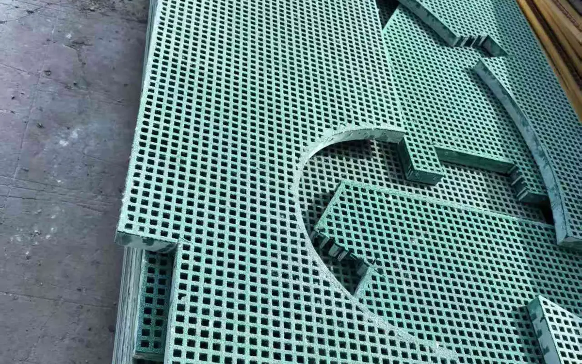
Factory cutting can reduce individual piece mass, but the split must preserve support, bearing direction and opening requirements. Dividing a panel into narrow strips can create a different local geometry and edge-support condition.
A useful load document should let the reviewer answer:
A high-level material test report can support the material but may not identify the complete panel model. An ultimate failure test is not automatically a service load. A tabulated allowable load is not automatically the point-load rating for an equipment foot.
Our own sample report HZTC/BG-24051102 records a 4 kN/m² equivalent uniform design-load test over a stated 600 mm span, with material results. Because it does not identify one complete model with thickness, mesh, bar section and resin, we use it as a material and sample record rather than a blanket load table for every row. Read the test-report applicability guide before attaching a report to a project.
Use one drawing to show every support, bearing face, panel joint and unsupported edge. Mark where the panel is fixed and where it can move or lift.
Measure between the actual support faces in each direction. Do not use the panel outline or frame center distance unless the source table explicitly uses that definition.
Start with the general traffic load, then add the local loads. If a trolley crosses only part of the route, its wheel path belongs on the drawing.
Write the project value and source. If it is not known, mark it as unresolved rather than assuming the most convenient limit.
Compare depth and mesh as one row. Include resin, surface and panel format because they affect the offered product and delivered mass.
Use a different table row for each configuration. Do not interpolate between depth or mesh values if the source does not permit it.
Mark cutouts, finished edges, clip locations and maximum piece mass. Revise the panel split if the handling plan requires it.
Connect the drawing revision, quotation, product row, finished-piece list, packing and required evidence. The page FRP grating specification template gives the field list for that file.
Pultruded grating begins with the bearing direction. Draw the bearing bars from one effective support to the other. Confirm the end bearing, cross-rod arrangement and any cut bar.
Then compare I, T and WT sections with the same span and load. Use the pultruded bearing-bar direction guide for the layout and bar spacing and open area guidance for drainage and object passage.
Confirm panel width and length from the production drawing. Pultruded panels can be custom-sized, so there may not be a standard stock outline to fall back on. Mark the nearest cross-rods, end offsets and any requirement to align adjacent panels.
Finally, check the bearing bars and panel pieces for handling. A long custom panel can be structurally appropriate and still need a defined lift and support plan before transport.
Our factory can make and cut molded and pultruded products across different rows, but the production question is broader than the depth. We need to know the actual product family, geometry, resin, surface, finished pieces and accessories before quoting a manufacturable item.
When a buyer asks for 25, 38 or 50 mm, we treat that as the start of the review. We want to know whether the frame already exists, how the panel will be supported, what load reaches the surface and how the finished pieces will be lifted. The answer may be a deeper panel, a different construction, a revised support spacing or a piece split.
That is the useful manufacturer contribution: connect the design input to a product we can actually produce and document. A page that only lists a universal thickness for each application would be easy to write and unreliable to use.
If a supplier cannot answer questions 6 to 10, the quotation may still be accurate for the panel it describes, but it is not yet sufficient for the project comparison.
Use 25, 38 and 50 mm to identify candidates. Use the support drawing, load case, deflection limit, exact product row, fabrication plan and matched evidence to approve one.
That approach lets the buyer compare offers fairly. It also lets the factory provide a product that can be built, lifted and documented, instead of turning one convenient number into a promise the panel cannot support.
Get a Quote
Factory rows
These rows show why the same nominal depth can represent different mass and structure.
| Nominal depth and product | Geometry | Listed mass | What the row establishes |
|---|---|---|---|
| Molded 25 mm | 38 x 38 mm mesh | 12.5 kg/m² | A shallow molded candidate with a specific mesh and panel format |
| Molded 25 mm tree-pit base | 40 x 40 mm mesh | 10.5 kg/m² | A confirmed tree-surround starting row, not a general platform rating |
| Molded 30 mm | 38 x 38 mm mesh | 16.5 kg/m² | A common factory starting row for pedestrian access review |
| Molded 38 mm | 38 x 38 mm mesh | 19.5 kg/m² | A deeper molded row, not a universal structural grade |
| Molded 50 mm standard | 50 x 50 mm mesh | 21.5 kg/m² | A standard 50 mm molded row |
| Molded 50 mm heavy duty | 25 x 50 mm mesh | 45.0 kg/m² | A separate heavy row with different construction and handling |
| Pultruded I25 series | 25 mm bar height, 40/50/60 mm pitch | 16.5 / 14.5 / 12.5 kg/m² | Directional bearing bars with the listed open-area geometry |
| Pultruded I38 series | 38 mm bar height, 40/50/60 mm pitch | 23.0 / 20.0 / 18.5 kg/m² | A different structural family from molded 38 mm grating |
| Pultruded T50 series | 50 mm bar height, 38/50 mm pitch | 20.5 / 16.5 kg/m² | A T-profile direction with its own bearing and load evidence |
Construction
The depth label sits inside a different geometry and load path in each family.
| Selection issue | Molded grating | Pultruded grating | Question to settle |
|---|---|---|---|
| Meaning of depth | Overall molded panel depth tied to the mold and mesh | Bearing-bar height tied to the I, T or WT series | Is the component measured the same way in each offer? |
| Primary load path | Connected grid distributes load in more than one direction | Parallel bearing bars carry the main span | Where will the load reach the bars or grid? |
| Direction | Square or rectangular mesh and possible long-way orientation | Bearing direction must run between effective supports | Does the drawing show direction and free edges? |
| Open-area choice | Mesh and panel row are selected together | Same depth can have 40, 50 or 60 mm pitch at different mass | Are drainage, retention and load compared simultaneously? |
| Handling | Full molded panels can be heavy and awkward | Custom-length panels and bar count change mass | Can the workshop and site handle the finished pieces? |
| Evidence | Must match the molded row, support and test condition | Must match the pultruded series, span and bearing direction | Can the source data be traced to this exact offer? |
Selection record
Eight fields connect the requested number to a panel that can be checked and fabricated.
| Selection record | Required input | Why it matters |
|---|---|---|
| Installation depth | Measured clear height including support, fixture and finished level | A deeper panel may not fit the existing frame |
| Support layout | Support faces, bearing width, joints, free edges and openings | Load enters the panel only where support exists |
| Clear span | Unsupported distance at each direction | Panel length and support center distance are not substitutes |
| Load case | Uniform, point, line, wheel or sustained load with units, contact area and position | Different load shapes can govern the same deck |
| Deflection limit | Absolute limit, span fraction or project criterion | A panel can be intact but too flexible for use |
| Exact product row | Molded depth plus mesh, or pultruded series plus pitch and bar size | Depth alone does not identify the structure |
| Surface and mass | Grit, cover or other finish and the resulting delivered mass | Finish changes handling and sometimes total height |
| Evidence source | Table, calculation or report with scope and conditions | A value cannot be transferred from another row |
Fit check
A depth becomes a candidate only after the installed and loading conditions are fixed.
RFQ checklist
Your drawing does not need every answer; it must make the unknown fields visible.
Evidence boundary
The final product record must prove more than the nominal depth.
This content was prepared and reviewed by Dengtai Industry’s technical and production team using the project conditions, available product data and applicable documents. Limits that require design, testing or approval are identified in the content. Content last checked:
Your choice is saved on this device. Cookie policy