Mini-mesh fabrication
Cut-to-Size Mini-Mesh Grating: Edges and Piece Identification
A finished mini-mesh piece is more than an outer dimension. The top face, both mesh layers, interrupted bars, support, sealed faces, piece mark and packed location have to match one drawing revision.
Prepared by
Dengtai Industry
Published
·
Reviewed

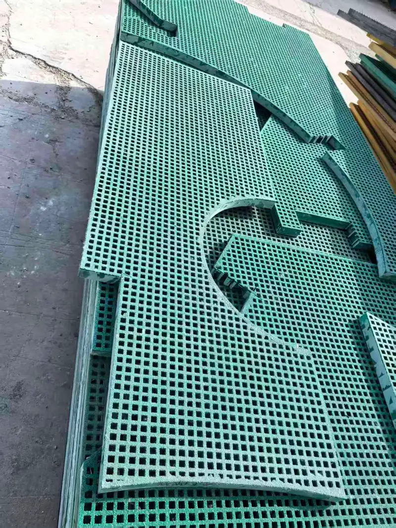
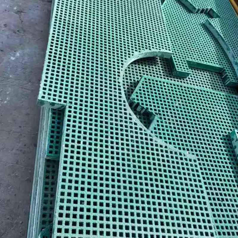
The cut outline, remaining bars, edge finish and piece mark are factory records, not finish observations made after packing. Photo: Dengtai Industry.
Fabrication vocabulary
Mini-Mesh Cutting, Openings and Piece Identity
A finished piece must preserve more than the outer shape.
- Cut-to-size mini-mesh piece
- A double-layer mini-mesh panel cut to the approved outline or with defined openings, then inspected and identified for its installation location.
- Outer trim
- A cut that changes the perimeter size or shape. It may remove complete small cells and expose both upper and lower mesh at the edge.
- Internal opening
- A cut-out inside the panel for a pipe, column, equipment or service. It can interrupt both mesh layers and the path to support.
- Datum
- The stated edge, centreline or reference point from which cut dimensions are measured. Every drawing dimension needs one.
- Mesh orientation
- The direction of the upper and lower grids and the intended top face. Rotation can change edge appearance, joint alignment and fixing fit.
- Edge sealing
- A compatible resin coating applied to exposed cut faces to protect the laminate. It does not reconnect a cut bar.
- Piece identification
- A unique mark connecting the finished piece to the drawing, location, quantity, packing list and any first-piece inspection.
- First-piece release
- The check made before repeating a cutting method. It confirms dimensions, edge quality, orientation and support scope on the approved revision.
Cut comparison
Perimeter Trimming, Internal Openings and Site Adjustment
The cut type changes the edge, support and record requirements.
Swipe horizontally to view all columns.
| Question | Perimeter trim | Internal opening | Site adjustment |
|---|---|---|---|
| Main change | Outer size or shape changes. | Bars and both mesh layers can be interrupted inside the panel. | A factory-cut piece is altered because the measured site condition differs. |
| Support review | Check remaining bearing edge and panel fit. | Check the support or frame around the opening. | Must be repeated against the revised measured condition. |
| Edge work | Seal the perimeter faces in scope. | Seal the opening faces, including irregular curves if agreed. | Requires an approved field method and documented change. |
| Piece identity | Keep the original piece mark visible. | Add an opening or feature reference where needed. | Record the field change against the original piece. |
Supply boundary
When Mini-Mesh Grating Should Be Factory Cut
Known geometry should be released with controlled orientation, sealing and piece marks.
Specify this if…
- The drawing revision and dimension datum are known.
- The top face and mesh orientation can be marked.
- Openings and support around them can be reviewed before cutting.
- Sealed faces and inspection scope can be stated.
- Every piece can be marked and packed to its location.
Look elsewhere if…
- The order relies on “cut to fit” without a measured drawing.
- A cut-out is treated as a cosmetic hole with no support review.
- Sealing is expected to restore a cut bar or the original capacity.
- Similar-looking pieces are left unmarked.
- Site fabrication is chosen when the dimensions are already known and the factory can perform the work.
Production fields
Eight Drawing and Release Fields for Mini-Mesh Cutting
Keep the two mesh layers, support and piece identity in one production record.
Swipe horizontally to view all columns.
| Drawing field | What to record | Why it matters for mini mesh |
|---|---|---|
| Revision and datum | Approved drawing, revision, dimensions and reference edges. | Two similar pieces can be offset by using different datum points. |
| Piece mark | Unique piece number, zone, quantity and handed/rotated status. | Similar mesh pieces can otherwise be installed at the wrong opening. |
| Top face and orientation | Walking surface, colour, grit and mesh direction. | Turning the piece can change the edge and clip fit. |
| Upper and lower mesh | Pitch, bar width, clear-opening basis and ordered lower layer. | An externally similar edge may come from a different construction. |
| Cut outline | Perimeter, curves, notches, corner radii and keep/cut side. | A cut line without a side instruction can preserve the wrong piece. |
| Opening support | Interrupted bars, remaining bearing, frame and fixing positions. | Sealing does not restore the load path removed by the opening. |
| Edge treatment | Faces to be sealed, cleaner, sealer and cure condition. | Every cut exposes laminate; “sealed on request” needs a defined scope. |
| Inspection and packing | First-piece check, defect record, mark location and package grouping. | Identity must survive handling, shipping and site storage. |
A cut mini-mesh panel is not identified by width and length alone. Two pieces can have the same outer size while using a different upper mesh, top face, opening support or handed orientation.
The production record must keep four things together:
- the approved drawing revision and datum;
- the mini-mesh row, both mesh layers and intended top face;
- the cut outline, interrupted bars and support around every opening; and
- the edge treatment, inspection result, piece mark and packed location.
If one of those items changes, the finished piece changes too.

Cutting Mini-Mesh Grating: The Short Answer
The cutting method depends on whether the work is an outer trim, an internal opening or a field adjustment:
| Work | Typical method | What must be checked |
|---|---|---|
| Long perimeter trim | Circular or track saw with a blade intended for composite material | Support both sides, follow the datum, allow for kerf and keep the top face oriented |
| Curves and notches | Jigsaw or reciprocating saw with a suitable blade | Support the waste piece, avoid twisting and inspect both mesh layers at the edge |
| Pipe holes and small cut-outs | Hole saw or drill for composite material | Mark from the actual item, support the exit face and check remaining bars and support |
| Edge clean-up | Light passes with an approved grinding or finishing method | Do not remove structural bars or grind into the bearing face |
Use dust extraction or good ventilation and appropriate eye, respiratory and skin protection. Follow the OSHA personal protective equipment guidance, the product safety information and the tool manufacturer’s instructions.
After cutting, check both mesh layers, dimensions, opening support and piece identity. Clean and dry the edge before applying a compatible sealer where that is specified. Sealing protects the cut face; it does not restore a cut bar.
The detailed generic FRP cutting guide covers blades, drilling and PPE. The sections below add the mini-mesh-specific production and release controls.
Start With the Difference Between a Trim and an Opening
An outer trim changes the perimeter. It removes complete cells and creates a new edge around the panel.
An internal opening interrupts the mesh inside the panel. It can remove upper bars, lower bars or both, and it can break the path by which load reaches a support. An opening close to an edge, support or fixing point can have a different consequence from the same opening at the centre of a well-supported panel.
Do not approve both cuts with one instruction such as “cut to size.” State:
- the finished outer dimensions;
- the position of every internal opening;
- which edges are datum;
- which bars may be interrupted;
- the required support around the opening; and
- the top face and mesh orientation.
The generic cutting and sealing guide explains tools, dust control, drilling and sealing. This page focuses on the mini-mesh-specific record that must follow the finished piece.
Why Mini Mesh Needs Its Own Edge Check
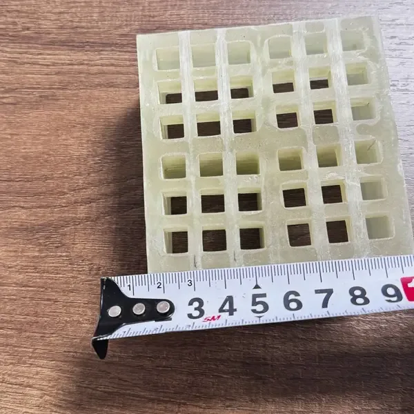
Mini mesh is usually a double-layer molded product. The visible upper mesh is finer than the lower support grid. A cut edge can therefore expose:
- small upper-bar ends;
- larger lower-grid sections;
- a gap or cavity between the layers;
- resin-rich areas, grit or surface build;
- a shaped opening where several bars end close together; and
- a different number of exposed bar ends per metre from a standard mesh panel.
A clean outer outline does not prove that both mesh layers are intact or that the remaining bars can reach the support. Inspect the top and underside where access allows.
Freeze the Drawing Before the Saw Starts
Dimension datum
Every finished dimension needs a datum. Measuring from a convenient edge on site can reverse or shift a piece that looks symmetrical in the panel photograph.
Mark the original datum on the approved drawing and on the first piece. Keep the keep side and waste side unambiguous.
Top face and mesh direction
The top face may include grit, colour and the finer retention grid. The lower mesh sits below it. Mark the face that must remain up, then mark the mesh direction or a reference corner so the piece is not rotated.
Two “identical” rectangles can be mirror images when an opening or edge treatment is handed.
Panel and opening support
Mark support faces, bearing width and the frame or added support around every opening. Confirm how the remaining bars transfer load.
The molded cut-out guide helps show why the hole size alone is not the structural review. The support-layout guide defines the bearing condition that must match the finished cut.
Edge-sealing scope
“Sealed edges” is incomplete. State whether the scope covers:
- the complete perimeter;
- internal opening faces;
- drilled holes;
- shaped curves and notches; or
- a combination.
The sealer must be compatible with the resin and surface. The face must be clean and dry before application. Sealing protects exposed laminate; it does not reconnect a bar.
Produce the First Piece as a Controlled Trial
Before repeating the cut:
- Compare the drawing revision and cut list.
- Mark the datum, top face and piece number.
- Support both sides of the panel securely.
- Follow the approved tool and cutting method.
- Check the finished dimensions and opening location.
- Inspect both mesh layers and the exposed bar ends.
- Confirm the remaining support and fixing positions.
- Clean and dry the face before sealing.
- Apply the sealer to every face in scope.
- Repeat the approved dimensions and quality checks.
The first piece should be photographable as a complete record: a scale or rule in one view, the piece mark visible, the finished edge in close-up and the relevant support/opening detail marked on the drawing.
Inspect the Cut Itself
Geometry
Check:
- finished outer dimensions;
- opening size and position from the datum;
- edge straightness or agreed curve;
- square or alignment;
- clear span and bearing;
- clip and drilling positions; and
- relation to adjacent pieces.
Edge quality
Look for:
- chipped upper or lower bars;
- torn fibres;
- resin burn;
- cracks;
- delamination;
- voids or exposed laminate;
- incomplete cutting that has been forced apart; and
- wax, dust or moisture left before sealing.
A poor edge cannot be corrected by a coat of sealer. Hold the piece and rework or replace it according to the approved process.
Orientation and identity
Check the top face, handed orientation and mesh direction. Then confirm that the piece mark is legible and matches the drawing and packing list. Put the mark where handling and packing will not remove it.
Seal, Cure and Handle in That Order
After cutting:
- remove dust and loose material;
- confirm the face is dry;
- mix the compatible sealer as instructed;
- coat every required face;
- inspect coverage before cure;
- allow the specified cure before stacking or handling; and
- protect the sealed edge in packing.
The exact sealer, coverage and cure are order-specific. Do not substitute paint or an unknown resin because it looks similar. A project-specific field method belongs in the fabrication record when the piece will be adjusted after delivery.
Factory Cutting vs Site Cutting
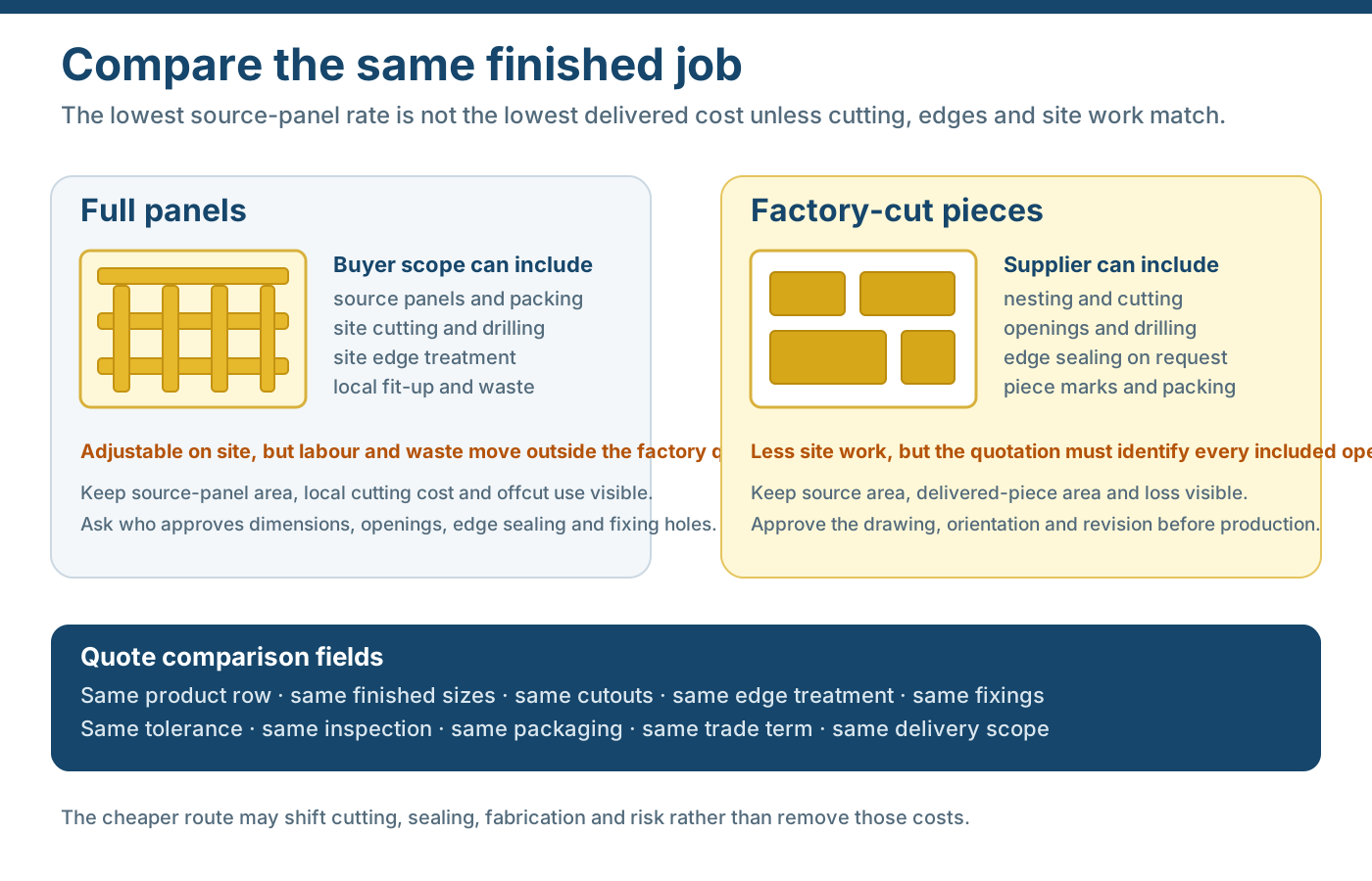
Factory cutting is preferred when:
- dimensions are known before production;
- the order repeats the same shape;
- top-face and mesh orientation matter;
- cut-edge sealing is required before dispatch;
- openings need a support review; or
- pieces must be marked and packed to specific positions.
Site cutting may be appropriate for a late field measurement or an approved repair/replacement. The site then needs:
- the same drawing revision;
- a measured first-piece trial;
- the correct tool, support and dust control;
- a compatible sealer;
- an inspector and acceptance record; and
- a means of updating the piece mark and as-built record.
Do not send an unmeasured site structure to the factory as a nominal size and later cut each piece by eye. Measure, revise and release. The cut-to-size FRP grating piece-list guide shows how to keep the two mesh layers, piece marks, openings and sealed faces under one controlled list.
Piece Identification Is a Safety Control
Similar mini-mesh pieces are easy to mix after packing. A usable mark should connect:
- piece number;
- drawing revision;
- quantity and location;
- top-face orientation;
- handed or mirrored status;
- opening references; and
- any hold or rework condition.
One workable label format is:
| Label field | Example |
|---|---|
| Piece | P-07 |
| Drawing | Rev A |
| Area | Zone 2 |
| Top face | Grit / brown, arrow to stair |
| Feature | Opening O-2 for 110 mm pipe |
| Status | Released after edge inspection |
This is an example of data to retain, not a quantity or project approval. Keep the real values on the drawing and packing list.
Pack identical pieces together only when they are truly interchangeable. Otherwise group by zone or piece mark. Keep the mark readable at receiving and during installation.

What the Factory Can and Cannot Confirm
We can confirm the offered mini-mesh row, the approved finished dimensions, the drawing revision, the agreed opening outline, available edge-sealing scope, available fixing positions and the piece-marking and packing scope in the order.
We cannot:
- approve a structural opening when the support is not defined;
- restore a cut bar by sealing it;
- turn an unsealed joint into a liquid-tight assembly;
- guarantee dimensions measured from different datum points;
- correct a wrong top face after cutting; or
- let an unidentified piece be matched to a location by eye.
The Cut-Piece Release Rule
Release a mini-mesh piece only when the drawing revision, top face, both mesh layers, support, sealed edge, inspection result and piece mark agree. The finished outline is the first check, not the last one.
Fabrication sequence
How We Turn the Drawing Into Marked Mini-Mesh Pieces
Work from one revision through cutting, inspection, sealing and packing.
Reconcile the revision, dimensions, quantities, piece marks, units and datum before production.
Keep the upper fine grid, lower layer and joint pattern consistent across the order.
Support both sides of the panel and work to the approved outline and opening position.
Look for chipped cells, torn fibers, delamination and bars that no longer reach a support.
Clean and dry the cut before applying the compatible sealer and allowing the specified cure.
Record the first-piece result, mark the piece and pack it by the approved location.
Release record
What Must Match Before a Cut Mini-Mesh Piece Ships
The drawing, edge, support and piece mark remain traceable through packing.

Drawing revision
The cut and the piece mark refer to one approved layout.
Orientation
Top face and mesh direction are visible before cutting.
Both mesh layers
The upper grid and lower structural layer are checked at the edge.
Opening support
Remaining bars and bearing path are reviewed around every opening.
Sealing record
Clean face, compatible sealer, coverage and cure remain traceable.
Piece identity
The same mark follows the piece into inspection and packing.
RFQ checklist
What to Send With a Mini-Mesh Cutting Inquiry
Include the drawing revision, both mesh layers, openings and edge scope.
- Approved drawing — Revision, plan/ elevation views, datum, dimensions, piece marks and quantities.
- Panel configuration — Mini-mesh row, both mesh layers, depth, resin, colour and surface.
- Cut scope — Perimeter trim, openings, notches, curves, corner requirements and keep side.
- Support and fixing — Bearing faces, support around openings, clips, holes and removable pieces.
- Edge treatment — Faces to be cleaned, sealed, coated or left untreated.
- Identification — Mark format, content and location where it remains visible after packing.
- Inspection — First-piece checks, dimensional record, edge acceptance and hold criteria.
- Packing — Grouping by zone, piece mark, orientation, protection and lifting information.
Request a cut review
Send the Cut List and Opening Support
We will compare piece identity, orientation, edge treatment and support before cutting.
- Drawing revision and datum checked
- Upper and lower mesh both inspected
- Piece marks tied to packing
Cutting Mini-Mesh Grating Questions
Can mini-mesh grating be cut to size?
Does cutting change the structural capacity?
Can a cut edge be sealed?
Why must every piece be marked?
Is factory cutting better than site cutting?
How do I check the cut edge?
Can an opening be sealed to restore strength?
What should be sent with a cutting quotation?
This content was prepared and reviewed by Dengtai Industry’s technical and production team using the project conditions, available product data and applicable documents. Limits that require design, testing or approval are identified in the content. Content last checked: