Mini-mesh fixing selection
Mini-Mesh Grating Clip Fit: Bar Width and Jaw Clearance
A clip for a standard mesh is not automatically a clip for a mini-mesh panel. Match the actual bar at the contact point, jaw opening, leg spacing, panel height, bolt path and support position.
Prepared by
Dengtai Industry
Published
·
Reviewed

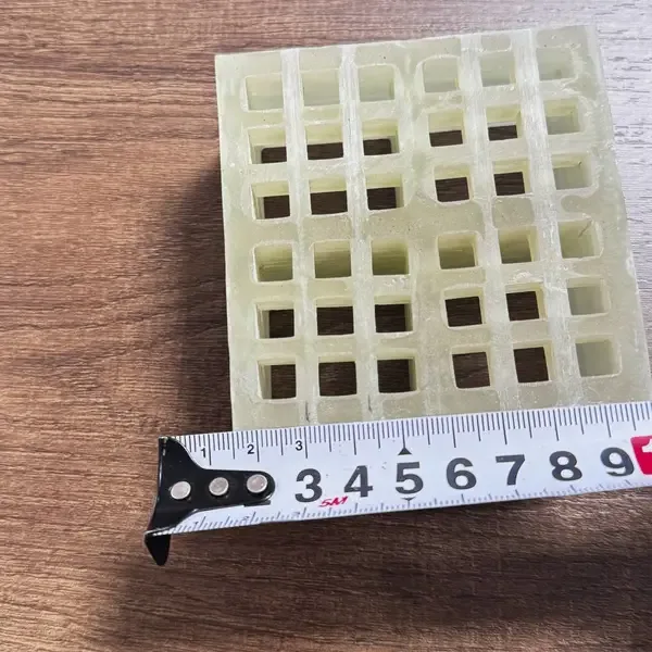
A factory fit photo on a molded sample. The mini-mesh order still needs its own bar and jaw check. Photo: Dengtai Industry.
Fixing vocabulary
Mini-Mesh Clip Terms and Contact Geometry
The clip family describes a shape; the measurement describes whether it fits.
- Hold-down clip
- A component that restrains the panel to its support. It does not increase the panel span or create a new bearing support.
- Panel connector
- A clip used at the joint between two panels to keep their edges aligned and limit relative movement.
- Bar contact width
- The width of the actual bar where the clip jaw lands, measured at the contact depth rather than inferred from the mesh name.
- Jaw clearance
- The unobstructed width and depth inside the clip jaw. It must let the bar enter fully without placing the jaw on the bar edge.
- Leg spacing
- The distance between the points or bars the clip spans. A clip designed around a wider standard opening may not settle into a small upper mesh.
- Clip height
- The vertical distance between the top contact and the support or bolt seat. It must suit the full panel depth.
- Trial fit
- A check on a representative sample that shows full jaw seating, stable contact and enough bolt and tool access without panel distortion.
- Fixing layout
- The support and edge positions where clips are required, including releasable fixings, panel joints and cuts.
Clip comparison
M, L and C Clips for Mini-Mesh Grating
Separate hold-down, edge restraint and panel connection before selecting the hardware.
Swipe horizontally to view all columns.
| Clip | Normal job | Mini-mesh check | Does not solve |
|---|---|---|---|
| M clip | Usually holds a panel down across two adjacent bars. | Jaw width, leg spacing and the actual top-bar contact plane. | Support span, load capacity or a missing support below. |
| L clip | Usually restrains one bar at an edge or lighter fixing point. | Contact on one small bar, seat depth and surrounding cover or edge trim. | A full two-bar hold-down job without engineering comparison. |
| C clip | Usually joins two panel edges and controls the step. | Both panel heights, top mesh, edge bars and support under the joint. | A structural joint or additional bearing. |
| J clamp with clip | Hooks beneath a support member where a through-bolt arrangement is unsuitable. | The jaw, upper-mesh contact, support flange and underside reach still have to match. | A complete fixing system unless the hardware and support detail are approved together. |
| Dome washer | Provides a top-side bearing area for certain fine-mesh or solid-top fixings. | The washer footprint, hole, screw, sealing and remaining mesh around the fixing. | Automatic equivalence to an M, L or C clip. |
| Countersunk screw | Produces a low-profile fixing in certain specified formats. | Whether the exact panel, laminate, surface and fixing location accept that detail. | An automatic choice for open mini mesh because the head can sit below the walking plane. |
Standard-clip boundary
When a Standard-Mesh Clip Should Not Be Assumed to Fit
A smaller upper grid changes the contact geometry even when the panel depth is unchanged.
Specify this if…
- The exact mini-mesh upper and lower construction is known.
- The actual bar at the clip contact point has been measured.
- The clip jaw and leg spacing can be trial-fitted to a sample.
- Panel height, support section and bolt access are known.
- The fixing positions come from the support and edge layout.
Look elsewhere if…
- A standard-mesh clip is selected because the clip name is the same.
- The upper mesh pitch is used as a substitute for bar width and jaw clearance.
- A clip is expected to increase load capacity or support the panel edge.
- The bolt cannot be reached from the installation side.
- A universal torque or clips-per-panel count is being assumed.
Fit record
Eight Measurements for a Mini-Mesh Clip Fit
Record the actual bar, jaw, height, support and fixing layout.
Swipe horizontally to view all columns.
| Fit field | What to record | Why it matters |
|---|---|---|
| Clip job | Hold-down, edge restraint or panel-to-panel connection. | Different functions require different contact and movement control. |
| Mini-mesh row | Upper pitch, upper bar width, lower mesh, total depth and surface. | The visible mesh and hidden structure are separate fields. |
| Contact bar | Bar width at the plane where the jaw lands, plus local taper. | A nominal bar size can leave the jaw on an edge. |
| Jaw geometry | Clear width, internal depth, leg spacing and seating length. | The clip must enter, seat and bear on the intended bars. |
| Height | Top of bar to support or bolt seat, including surface build. | A clip that is too shallow or too tall distorts the panel or leaves it loose. |
| Bolt path | Bolt diameter, length, washer, nut, support thickness and tool access. | A visually correct clip can be impossible to fasten from the site side. |
| Trial fit | Contact marks, rocking, distortion, full seating and clearance. | It confirms geometry that the catalogue name cannot. |
| Layout | Supports, edges, joints, cuts, removable panels and exposure. | Fixing quantity and positions come from restraint requirements. |
Mini-mesh clips are not selected by the letter alone. An M clip for a standard molded panel and an M clip for a finer upper mesh may look similar while presenting different jaw widths, leg spacing and contact positions.
The fit that matters is the place where the metal actually meets the bar. If the jaw lands on a narrow edge, bridges the opening or pulls the top grid out of shape, the fixing may look installed while failing to provide the intended restraint.

Why the Mini-Mesh Upper Grid Changes the Fixing
A standard M clip usually spans two adjacent bars. On a 38 mm or 40 mm upper mesh, those bars sit at the spacing the clip was designed around. A mini-mesh panel introduces a second, finer top grid and can reduce the clear opening to around 12.5 mm or less.
That changes several things:
- the jaw may not pass between the upper bars;
- the clip legs may land on the wrong side of a bar;
- the contact may occur on a small top bar instead of the intended pair;
- the bolt path may be obscured by the upper layer;
- a C connector at the panel edge may need a different edge-bar engagement; and
- tightening can distort the finer grid before it reaches a stable hold-down.
Our current mini-mesh rows include 11 × 11 mm, 19 × 19 mm and 20 × 20 mm upper pitches with different bar widths. Those labels do not define a universal clip. The exact row and the contact geometry must be matched to the hardware.
Measure at the Contact Plane
Do not measure only the top surface opening and do not rely on the nominal bar width from a catalogue. Record:
- the upper pitch;
- the bar width at the depth where the jaw seats;
- the clear opening around that contact point;
- the lower mesh or support structure beneath it;
- the full panel depth;
- the clip jaw clear width and internal depth;
- the distance between the clip legs or contact points; and
- the bolt length, hardware and support access.
The upper mesh may taper. Surface grit or resin build may also affect the effective plane. A square cut sample and a rule are enough to start, but the manufacturer or fabricator should confirm the measuring method used for release.
Trial-Fit the Complete Assembly
The most useful clip evidence is a trial fit on a representative panel. Put the actual clip on the actual mesh row and support section, or an agreed equivalent.
Accept the fit only when:
- both contact points or jaws seat on the intended bars;
- the clip does not rock across the opening;
- the legs do not bridge the fine top grid without contact;
- the clip height suits the total panel depth;
- the bolt can be inserted, reached and tightened;
- the panel remains flat and the upper mesh does not visibly crush; and
- the fixing can be removed and refitted without changing position.
Photograph the fit from above, the side and underneath if access allows. Mark the sample with the mini-mesh row and clip reference. A close-up photograph without scale can show contact, but not whether the jaw is wide enough for a replacement order.

M, L and C Solve Different Restraint Problems
M clip
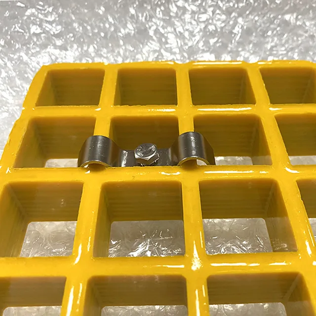
The M clip normally holds the panel to a support across two adjacent bars. On mini mesh, the key checks are the jaw, leg spacing and whether the contact occurs on the intended bars rather than the openings.
L clip
The L clip bears on one bar. It can suit an edge or lighter fixing position, but it is not automatically equivalent to an M clip. On a small upper mesh, the single-bar contact area and clearance around the bolt require their own check.
C clip
The C clip aligns two panel edges. The second panel and the support under the joint matter as much as the clip itself. A connector does not carry the panel and does not replace a bearing support.
Some suppliers use mini-mesh-specific M clips or alternative top fixings such as dome washers and countersunk screws. We do not translate those names into our standard range without confirming the actual hardware and bar contact. Our clip family guide explains what M, L and C normally do; this page explains why mini mesh needs a separate fit review.
J clamps and top fixings are separate systems
A J clamp normally hooks beneath a support member and may be used with a clip where a simple through-bolt arrangement is unsuitable. It still has to match the mini-mesh jaw, the upper-bar contact and the support geometry. The ability to hook under a beam does not prove that the top-side clamp seats correctly.
A dome washer or countersunk screw changes the fixing from a spanning clip to a local top fixing. That introduces its own checks: hole position, remaining upper and lower bars, load path to the support, sealing, head or washer projection, and whether the selected panel is approved for that fixing. We do not treat any of these as interchangeable with an M, L or C clip.
Drilling and top-side fixings need their own review
A drill or countersunk screw removes material from the upper mesh and may pass through one or more structural bars. Before that fixing is accepted, check:
- the hole location against the upper and lower mesh;
- which bars are removed and how load reaches the support;
- edge distance to a panel joint, cut edge or open cell;
- the washer or screw-head footprint;
- sealing of the drilled wall and walking surface; and
- whether the manufacturer permits that fixing in the specified format.
Do not use a generic screw that happens to fit the opening. A top fixing that cuts the fine upper bars can create both a small opening defect and a larger structural or corrosion-maintenance question.
The clip material belongs to the exposed assembly
Galvanized steel may be adequate for a dry or lightly exposed indoor route. Stainless steel is often relevant to marine, frequent wash-down and chemical areas, but “stainless” is not a complete grade specification. Confirm the grade, fastener material and contact with the steel support together.
Water trapped around a clip, damaged galvanizing or incompatible metals can shorten the assembly’s service life even when the FRP panel remains sound. Record the environment with the fixing selection rather than choosing the least expensive metal at the quotation stage.
Do Not Turn a Fit Issue Into Over-Tightening
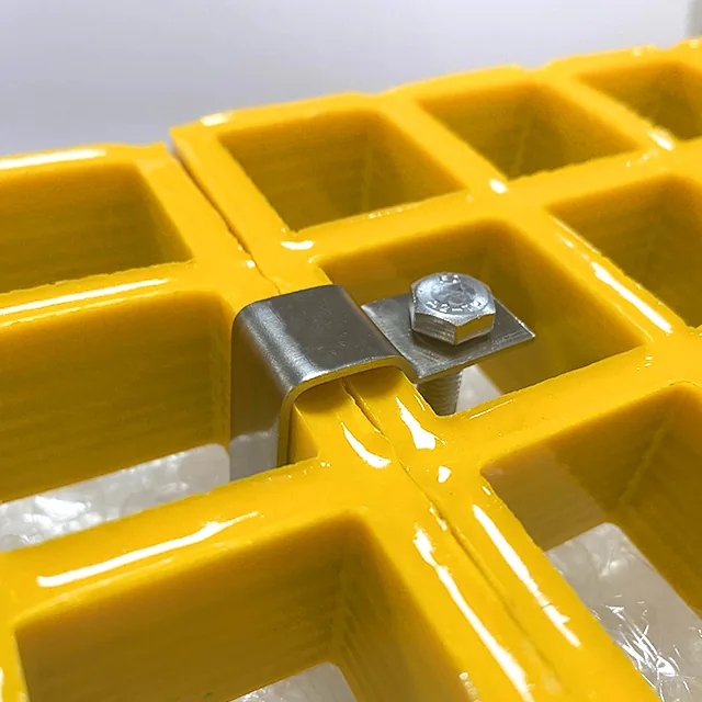
If a clip is partly seated, tightening harder will not make the jaw fit. It can:
- crush the resin around the upper bar;
- distort the fine grid;
- lift the panel at another edge;
- bend the clip;
- reduce contact on the support; or
- hide the original mismatch under visible deformation.
Use the hardware supplier’s tightening instruction for the actual assembly. We do not publish a universal torque figure because bolt, washer, clip material, support section and panel construction differ. “Tight until the panel deforms” is not a method.
The Clip Count Comes From the Layout
The number of clips is not a fixed number per mini-mesh panel. It comes from:
- the number and position of supports;
- panel size and orientation;
- perimeter edges requiring restraint;
- panel-to-panel joints;
- cuts and openings;
- wind uplift or equipment movement;
- wash-down and maintenance handling; and
- whether panels are removable.
Place a clip on a real support or edge condition. A fixing in the middle of a bay has nothing to transfer restraint into. The installation guide places the fixing review after supports and panel layout, where it belongs.
What the Factory Can Confirm
We can confirm:
- the mini-mesh row and stated upper and lower mesh fields;
- panel depth and dimensions;
- available M, L and C clip families in the agreed order scope;
- the clip height against the offered panel;
- trial fit on a representative sample where agreed;
- the support and fixing positions shown on the approved drawing; and
- whether a different fixing detail remains outside our standard supply.
We cannot confirm a clip from a product name alone, extend the panel span with extra clips, certify an untested torque, or make a standard clip fit a mini-mesh row by substituting the nearest item in the carton.
A Practical Clip-Release Record
- Record the ordered mini-mesh row.
- Record the actual contact-bar geometry.
- Record the jaw and leg measurements.
- Mark the clip function and positions.
- Trial-fit on the panel and support.
- Check bolt and tool access.
- Confirm the material and hardware.
- Photograph the approved sample.
- Keep the clip, panel and drawing revision together.
The Clip-Fit Rule
A mini-mesh clip is approved when it seats on the actual bar, reaches the actual support and restrains the intended panel without distortion. The M, L or C name is useful only after that physical fit is proven.
Fit sequence
How to Check a Mini-Mesh Clip on the Actual Panel
Start with the clip job and finish with a controlled trial fit.
Separate hold-down from panel connection before comparing M, L or C shapes.
Record upper pitch, bar width, lower mesh, depth, surface and ordered edge condition.
Check clear width, depth, leg spacing and full seating on a representative sample.
Confirm the clip suits the total panel depth and can reach the actual support.
Use support lines, edges, joints and removable pieces to set quantity and locations.
Release only after a controlled fit check with the approved hardware instructions.
Evidence map
What Must Match Before a Mini-Mesh Clip Is Released
The clip and panel need a shareable fit record.

One exact panel row
Upper mesh, bar width, lower layer and total depth.
One clip geometry
Jaw width, depth, leg spacing and overall height.
One trial fit
Full seating and repeatable contact on a sample.
One fixing location
The clip must be above a real support or edge detail.
One bolt plan
Length, hardware and installation access are checked.
One restraint record
Quantity and tightening instruction stay visible in the order.
RFQ checklist
What to Send With a Mini-Mesh Clip Inquiry
Include the ordered mesh, fixing detail and support access.
- Ordered mini-mesh row — Upper pitch, bar width, lower mesh, depth, panel size, surface and edge format.
- Clip function — Hold-down, edge restraint or panel connector, with the locations marked.
- Jaw dimensions — Clear width, internal depth, leg spacing and seating length needed for the panel.
- Height and hardware — Total panel depth, clip height, bolt diameter/length, washers and nut.
- Support — Section, thickness, material, bearing width and access from below or above.
- Layout — Support lines, panel joints, cuts, removable pieces and exposure.
- Material — Galvanized or stainless direction and the exposure or grade requirement.
- Evidence — Sample fit, drawing, hardware instruction or agreed installation method.
Request a fit review
Send the Bar, Clip and Support Conditions
We will check the actual contact geometry rather than the letter alone.
- Actual bar width checked
- Jaw and leg spacing verified
- Fixing count based on the layout
Mini-Mesh Grating Clip Questions
Can I use a standard M clip on mini-mesh grating?
Is bar pitch the same as jaw width?
Why can a clip appear tight but still be wrong?
What torque should be used?
How many clips does a mini-mesh panel need?
Does a clip increase the panel load capacity?
What if the mini-mesh opening is too small for an M clip?
Are J clamps, dome washers or countersunk screws interchangeable with M clips?
What should I send for the first clip review?
This content was prepared and reviewed by Dengtai Industry’s technical and production team using the project conditions, available product data and applicable documents. Limits that require design, testing or approval are identified in the content. Content last checked: