Grating fixing responsibility
Grating Fixing Interfaces: Who Confirms Clips, Bolts and Supports?
The grating supplier can confirm the panel-fit geometry and supplied fixing scope. The supporting structure, desired restraint and final connection still need a named project owner. Confirm all five layers before a panel-and-clip package is released.
Prepared by
Dengtai Industry
Published
·
Reviewed

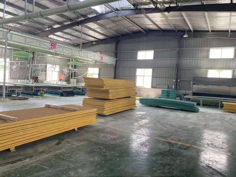
An installed route shows why panel fit, support geometry and project-level connection design must be reviewed together. Photo: Dengtai Industry.
Interface terms
The Five Layers of an FRP Grating Fixing
Define the layers first, then assign each one an owner and an approval record.
- Fixing interface
- The boundary and contact path between the grating panel, clip, fastener, support and supporting structure. Each layer can belong to a different supplier, engineer or installer.
- Structural support
- The beam, angle, channel, rail, kerb or frame that bears the panel and receives the fixing. Its capacity, position and attachment to the larger structure must be designed for the project.
- Grating clip
- A shaped component that restrains a panel at a support or joins adjacent panel edges. It transfers only the action the approved fixing detail asks it to transfer.
- Fastener
- The bolt, screw, stud or other hardware that links the clip to the support. Length, grade, thread, washer and access all form part of the connection rather than optional accessories.
- Support connection
- How the support itself is fixed into the building or equipment structure. This is outside a grating clip’s function unless the project scope explicitly includes the support assembly.
- Interface record
- One drawing-linked record listing panel mark, fixing ID, clip type, fastener, support reference, material, access, documents and exclusions.
When to formalise it
Use a Fixing Interface Record When Responsibility Is Shared
It is especially important where several parties design, supply and install the completed platform.
Specify this if…
- Several parties supply or approve the panel, clips, fasteners and support, and their boundaries are not yet written down.
- The support is an angle, channel, tube, rail, kerb or frame whose section affects whether the clip can seat and the bolt can be reached.
- The fixing has to resist uplift, vibration, movement or repeated removal as well as hold the panel in place.
- The project has top-side-only access, limited room below, or another installation constraint that changes the fixing method.
- A previous installation left panels loose, fasteners incomplete or clips fitted between supports because responsibility was assumed.
Look elsewhere if…
- The drawing already contains a fully dimensioned, approved fixing assembly and the task is only to supply an identical catalogued component.
- Someone expects a clip manufacturer to approve the support beam, its anchoring or the load capacity of the complete platform from a photograph.
- A standard clip letter or bolt diameter is being treated as proof of structural adequacy.
- A substitute support, hole position or fixer is being accepted without checking the approved assembly.
Responsibility
Supplier, Project Engineer and Installer Roles
The same physical fixing crosses more than one commercial scope. Write the boundary down.
Swipe horizontally to view all columns.
| Interface layer | What the grating supplier can confirm | What the project side must confirm |
|---|---|---|
| Grating panel | Supplied height, bar or bearing-bar geometry, panel edges, marks and finished-piece dimensions | Required structural duty, span, design load and complete platform arrangement |
| Clip | Offered jaw and height, intended hold-down or joining task, supplied base material and available quantity basis | Whether that clip is approved for the required movement, uplift, environment and fixing detail |
| Fastener | Included or excluded hardware scope, available length and material options | Required grade, diameter, locking detail, corrosion compatibility and tightening requirement |
| Support | Fit information needed to assess the clip-to-support contact | Support section, thickness, material, cutouts, coating, capacity and structural attachment |
| Structure and completion | Product and supplied-accessory records within the agreed order scope | Structural design approval, installation acceptance, inspection and sign-off |
Review method
Confirm an FRP Grating Support Connection in Five Steps
Keep product fit, structural design and installation evidence in one review sequence.
Start with the ordered panel type, height, bar geometry, panel marks and current support drawing. A record against a superseded layout is not an approved interface.
Mark the panel, clip, fastener, support and the support’s connection to the structure. Identify any layer not in the purchase scope.
Record who approves the structural support, restraint criterion, fixing assembly, material, installation method and final inspection.
Confirm the jaw contact, bolt path, support section and available top or below access as one installation condition.
Any change to clip type, fastener, support hole, panel mark or position should return to the interface record for approval before production or installation.
What an FRP Grating Fixing Interface Includes
An FRP grating bolt and support connection is not one product. It is a stack of decisions. The panel has a height and a bar geometry. The clip has a jaw, a contact area and a direction. The fastener has a diameter, length, material and locking detail. The support has a section, thickness and hole position. The support also has its own connection to the building, vessel, skid or primary frame.
Each layer can belong to a different party. On a typical export project, the platform designer approves the steel arrangement, the buyer selects the grating, the factory makes the panel and supplies the matching clips, the installer fits everything on site, and the client’s engineer accepts the completed access structure. If the quotation says only “panels with clips”, none of those boundaries is visible.
This page focuses on the interface. The M, L and C grating clip guide already explains what the common clip families look like and how their jaws differ. The clip layout and quantity guide shows how to number fixing positions from the support drawing. Here, the question is who confirms each layer and what evidence should survive the quotation and installation.
For a solar walkway, that same stack continues through rail brackets, roof anchors and waterproofing; use the solar walkway fixing-interface guide to keep those ownership boundaries separate from the grating clip.

A working definition
For a purchase order, we define the fixing interface as the complete contact path between the ordered panel and the structure that ultimately carries it. It includes the panel-to-clip contact, the clip-to-fastener contact, the fastener-to-support contact and the support-to-structure connection. It also includes installation access, material compatibility and the records that show what was supplied and fitted.
That definition prevents two common errors. The first is to ask the clip supplier to approve a support they have never seen. The second is to let an installer choose a different fastener because the one supplied does not reach through the support. Both errors make the line item look complete while leaving the connection unapproved.
The Responsibility Boundary Buyers Should Write Down
The useful commercial boundary is not simply “grating factory” versus “customer”. It follows what each party can actually see and control.
The grating supplier can confirm the product geometry being supplied. For example, we can check the panel height, the bar geometry available at a fixing point, and whether the jaw of the proposed clip seats on that panel. We can identify whether a bolt, nut or washer is included in our offered hardware set and state the material or coating of those supplied parts. We can carry agreed panel marks through fabrication and packing and show the fixing arrangement on the approval drawing. A request for one numbered fixing packet per panel is a separate packing method; it must be confirmed and quoted before production rather than assumed from the panel order.
The project engineer or buyer must define the action the fixing has to resist and approve the structure that receives it. That includes the support size and capacity, the support spacing, its connection to the main frame and any wind, vibration, impact, thermal movement or intentional lifting requirement. If the project requires sliding points, isolation washers, a particular bolt grade, a tightening method or a tested assembly, those inputs belong in the design record.
The installer controls the final physical evidence. They must confirm that the support is in the expected position, the panel is fully bearing rather than forced flat by the clip, the correct fixing ID is installed with the specified components, and any removable panel is restored in its marked order. A deviation should return to the project owner; it should not be corrected by adding an unapproved fastener or extra torque.
Make the omission explicit
A clear offer can state:
- Included: grating panel, hold-downs and connectors at the scheduled positions, specified fastener and washer components, marked packets and agreed documents.
- Excluded: structural design of the support, support anchoring to the primary structure, site access, installation labour and final project acceptance.
- To be confirmed: support section, hole location and diameter, installation access, tightening requirement, material compatibility and any uplift or movement criterion.
Those three lists are more valuable than a broad promise that a “complete fixing solution” is covered. The distinction lets the buyer price the missing work and lets the responsible engineer approve it.
How Support Geometry Controls Clip Selection
The support is not background information. It changes which fixing can work.
A steel angle presents an accessible horizontal leg and an outside edge. A hollow-section rail provides a closed top with different access below. A channel lip can limit the space around the jaw or washer. A tube may require a specific saddle or through-fixing arrangement. A concrete kerb may use a different anchor and should not be treated as if it were a drilled steel flange. The support thickness also changes the bolt length and may make a standard assembly unusable.
The support’s position controls the fixing location. A hold-down must land where the panel contacts a real support. Moving a clip a few centimetres to align with a convenient mesh opening can place it in midspan, where there may be no structure to fasten into. A panel connector at a joint also does not create bearing support. For a whole-platform check, see the fiberglass platform grating guide.
Installation access is part of geometry. If the installer can reach both sides, a through-bolt may be possible. If access is only from the top, the fastening method must be chosen for that route. A drawing that shows a bolt passing through an inaccessible hollow section has not solved the connection simply because the bolt appears on paper.
Top-side fixing is not one universal method
A top-side fixing can mean several different arrangements: a shaped bracket that grips an accessible flange, a clamp tightened from above, or a captive or threaded component that reaches a prepared support. These are not interchangeable, and no-drill claims should name the support geometry they require.
Before accepting a top-side detail, check that the jaw or clamp can reach the actual beam edge or flange, the support thickness suits the device, the panel bar remains in full contact, and the installer can tighten or release the fixing with the tools available. Check what happens if the flange is wide, tapered, coated, hollow or too deep for the tool. A device that depends on friction also needs the project to confirm the surface condition and the movement or uplift duty.
If the support is a box section, recessed rail, concrete kerb or an inaccessible flange, a standard clip cannot be assumed to convert it into a top-fix detail. The feasible method may need a different bracket or a project-specific connection. We can confirm whether our offered clip fits the ordered panel; the project still has to approve the support interface and installation method.
One panel does not imply one support detail
The same order can contain a fixed panel on an angle support, a removable cover over a tray and a pultruded panel on narrower beams. The clip record should therefore refer to support type and fixing ID, not only to the grating product. On a pultruded panel, the bearing-bar direction adds another constraint; the pultruded grating clip location guide covers that fit in detail.
Bolts, Fasteners and Tightening: Where Generic Advice Stops
It is reasonable to explain that the clip must contact the intended bars and that over-tightening can crush or distort the panel. It is not reasonable to publish one torque value for every panel, clip, bolt, washer and support combination. The correct value, if one is required, belongs to the approved hardware system and the project’s installation instruction.
A complete fastener line should identify the bolt or screw type, diameter, length, grade or coating, nut and washer. It should say whether a locking nut, thread-locking method or isolation washer is included. It should also consider thread engagement and support thickness. A stainless clip with a galvanized bolt is not a fully stainless connection; the clip material selection guide explains why every exposed component belongs in the same exposure review.
The installer also needs the correct working sequence. Seat the panel first. Trial the clip without forcing the jaw. Confirm the bolt reaches the support and can be turned with the specified tool. Then tighten only to the approved requirement. If the panel is rocking because the support is high or low, adding force at the clip can create local deformation instead of correcting the support condition.
Our factory rule is simple: do not substitute a bolt, omit a washer or add a drilled hole without returning the change to the fixing record. A small hardware change can alter the contact path, the material compatibility and the evidence package.
Clip profile and walking clearance
The top profile of the fixing belongs to the platform review when trolleys, carts, bags or cleaning equipment use the surface. A raised clip, exposed thread or projecting washer can catch a wheel, snag packaging, collect debris or become a trip point even when it holds the panel correctly.
Ask whether the detail needs a low-profile or recessed form, whether the panel geometry can accept it, and how the installer will reach and service it. Do not sink or modify a clip on site, omit a washer or reverse the assembly simply to make it sit lower. Any change that alters the contact or removal method must return to the approved fixing detail. After installation, inspect the completed route for raised threads, sharp projections, loose components and anything that can catch footwear or equipment.
What the Factory Needs Before It Releases the Fixing
We prefer a small, complete input set to a long email with conflicting photographs:
- Current panel schedule: product family, height, bar geometry, edge condition, surface and piece marks.
- Current support plan: beam or frame positions, section and thickness, hole positions if already designed, and the support material.
- Fixings marked on that drawing: each hold-down, edge restraint, panel connector and removable-set ID.
- Access route: whether installation and tightening happen from above, below or both.
- Action on the panel: ordinary restraint, traffic, vibration, wind or negative pressure, wash-down, equipment movement or frequent removal.
- Exposure and adjacent metals: the medium, salt, cleaning, temperature and the support material or coating.
- Approval owner: who accepts the structural design, material choice, tightening requirement and any deviation.
If any of these is missing, we can still quote the panel and the proposed accessory, but we identify the missing item as an assumption or an exclusion. This is deliberate. An apparently complete invoice should not be mistaken for an approved structural connection.
Where several supports, equipment openings and removable panels occur on one platform, use the platform opening and panel schedule guide to keep the fixing IDs tied to the same finished-piece records and drawing revision.
Keep the revision in the identifier
We recommend a fixing record that uses the panel mark, a drawing revision, a fixing ID and a support reference together. For example, P-03 / Rev B / M07 / S-02 is more useful than “M clip, 20 pieces”. It tells production which panel, installation which support and inspection which point. The installation guide explains how this record sits alongside panel layout and cutouts.
A Practical Review Sequence for a Platform
Begin with the platform boundary, not the accessory. Identify where people stand, what the panel carries, where the exposed edges are and which pieces will be lifted. Then mark the support lines and the panel boundaries. Only after those lines are visible should fixing points be numbered.
Next, assign a type to each numbered point. A point on a support can be a hold-down. A panel-to-panel line can need a connector. An exposed edge may need restraint or trim. A removable piece may use the same clip family as a fixed panel but needs its own component set and reinstatement identification. Do not total all three types into an undifferentiated “clip quantity”.
Then check the installation method. Look at the support section, the available tool space and the direction from which a person can work. For an offshore, roof or solar installation, the natural platform planning links and relevant application page may impose access restrictions that a workshop drawing does not show.
Finally, attach the evidence. The quotation should show the included accessories and exclusions. The approval drawing should show the fixing schedule. The packing list should identify the packet. The installation record should say the required IDs were fitted, seated and checked. If the support or fixing has changed, the record should show who approved the change.
What the Quotation and Drawing Should Show
A defensible quotation has separate visible lines for the panel, each fixing family, the hardware scope, material or coating, any special packing and the agreed documents. It does not need to publish a universal price or a universal count. It does need to make the basis auditable.
For a panel-and-clip offer, the description should say whether the fixing price is per clip body, per complete assembly, per numbered fixing point or per finished panel set. It should state whether bolts, nuts and washers are included. It should state whether non-standard drilling, edge treatment, labels or spare components are additional. The companion clip quotation comparison guide shows how to normalise those bases.
The drawing should carry the same information in physical form. Referencing “standard clips” is not enough when two supports on the same platform have different sections or access. A review against the current revision should show every support crossing, edge restraint and joint, and should reveal any fixing position that cannot reach structure. That is the point at which an engineering issue can still be corrected before panels and packets are made.
For the document side, keep the approved configuration, any supplied clip material statement, packing record and project acceptance record together. The quality and documentation guide explains the difference between a product record and a structural approval. The former can prove what was supplied; the latter belongs to the responsible project authority.
Inputs
What Must Be Known Before the Fixing Is Released
Each input changes geometry, hardware, access or evidence.
Swipe horizontally to view all columns.
| Confirmed item | Why it changes the fixing | Evidence to keep |
|---|---|---|
| Support section and thickness | Determines the contact surface, bolt length, hole location and whether a flange or saddle form can seat | Dimensioned support detail and current drawing revision |
| Access from above or below | Decides whether the installer can reach and hold the fastener and whether a top-fix assembly is required | Installation notes or a marked access route |
| Restraint requirement | Separates simple panel location from uplift, vibration, traffic or movement accommodation | Project design note, load direction and acceptance criterion |
Applications
Fixing Interfaces in Real Platform Conditions
Different supports and access routes produce different fixing questions.
Steel-angle platform with access below
A familiar saddle-style hold-down may suit the support contact, but the bolt length and the structural attachment of the angle still require confirmation.
Top-side-only maintenance access
Start with the installation route rather than the clip letter. A top-fix device changes the hardware, contact and removal procedure.
Pultruded grating on narrow beams
The bearing-bar orientation and support width control where a fixing can land. Check the pultruded clip fit before accepting a molded-panel detail.
Wet-process walkway
The panel is corrosion resistant; the clip, bolt, washer and steel support are not automatically one material family. Keep the complete exposed assembly in the record.
Removable inspection cover
The fixing has to be releasable, identifiable and refittable, with a component set that returns to the same marked panel.
Custom-cut panel with an opening
A cutout changes edge restraint and may introduce a frame or extra support. The clip schedule must follow the finished-piece drawing.
RFQ checklist
What to Send for a Grating Fixing Review
A complete drawing is more useful than a close-up photograph without dimensions.
- Panel schedule — Product family, height, bar or bearing-bar geometry, surface, panel and finished-piece marks, quantities and current revision.
- Fixing schedule — Every hold-down, edge-restraint and panel-connector ID with type, coordinates, support reference, quantity and removable-set mark.
- Support detail — Section, thickness, material, coating, hole position, support spacing and the support's connection to the primary structure.
- Installation constraint — Top or below access, available tool space, lifting equipment, traffic closure, required tightening method and who completes the check.
- Exposure and material — Chemical, salt, wash-down, temperature and adjacent metals for the clip, fastener, washers and support contact.
- Document and approval owner — Required drawing, certificate, test record, inspection record and the person or organisation approving deviations.
Factory position
Confirm Fit Without Pretending to Certify the Structure
Clear scope protects both the buyer and the finished installation.

Fit is a supplier question
We can confirm whether the proposed clip suits the supplied panel geometry and can show the hardware scope offered.
Structural duty is a project question
The support design, action on the panel and acceptance of the complete connection require the responsible project engineer.
Installation is an evidence question
A completed platform needs a record that every required ID was installed, seated and checked, including restored removable pieces.
Review route
From Fixing Detail to Approved Supply Scope
Unowned inputs are returned for confirmation rather than buried in an assumption.
Share the panel schedule, support drawing, fixing IDs and installation access. A photograph may explain the condition but does not replace dimensions.
We compare the offered clip height, jaw and hardware with the supplied panel and flag missing support dimensions.
Anything outside the panel and supplied-accessory scope is returned as an explicit project input or exclusion.
The panel mark, clip type, support reference, material, hardware and quantity are checked before production.
Panels and agreed accessories are checked against the approved packing list. Any panel-marked fixing packets must be separately confirmed and included in the order before their labels and counts are checked for dispatch.
Request a review
Send the Panel, Support and Fixing Detail
We will identify the panel-fit information we can confirm and the project inputs that remain yours.
- Molded and pultruded grating produced in house
- Full panels or factory cut-to-size pieces
- No fixed minimum order quantity
FRP Grating Bolt and Support Questions
Can you confirm which bolt and support I need from a photograph?
Does an M clip make the panel-to-support connection structural?
Can a standard clip be used with every support section?
Can every grating clip be installed from above without drilling?
Who should approve a substitute clip or bolt?
Do you supply the support frame and its structural connection?
This content was prepared and reviewed by Dengtai Industry’s technical and production team using the project conditions, available product data and applicable documents. Limits that require design, testing or approval are identified in the content. Content last checked: