PV fixing interface review
FRP Solar Walkway Fixings: Panel, Rail and Roof Interfaces
A solar walkway fixing is not one clamp. Separate the grating-to-clip connection, clip-to-rail fit and rail-to-roof attachment, then state who supplies, installs, seals and approves each layer.
Prepared by
Dengtai Industry
Published
·
Reviewed

A solar maintenance route. The grating clip is only one point in the complete fixing path. Photo: Dengtai Industry.
Fixing vocabulary
Four Interfaces Hidden Inside “Walkway Fixings”
The panel, clip, rail and roof attachment have different fit and responsibility questions.
- Panel fixing
- The connection that restrains the grating against the rail or other support. It does not create bearing or increase the support span.
- Grating clip
- A shaped accessory such as an M, L or C clip. The letter describes the form; the jaw, bolt and height must still match the actual panel and support.
- Rail or mounting track
- The member that supports the panel and transfers its load to a bracket or the roof structure. Its capacity and attachment are separate from the grating.
- Bracket or L-foot
- A connector between the rail and the roof or array structure. It can set walkway elevation, slope and adjustment.
- Roof attachment
- The roof hook, anchor, clamp, ballast or strut base that connects the support to the building. Its structural and waterproofing acceptance belongs to the roof-system designer.
- Penetrative fixing
- A solution that enters the roof covering or structure. The hole, anchor, sealing and reinstatement must be part of an approved roof detail.
- Non-penetrative fixing
- A solution that resists movement without a roof penetration. It still needs a load path, uplift restraint and roof-system approval.
- Uplift restraint
- The arrangement that prevents the walkway from lifting under wind or other upward action. The project determines uplift; the supplier cannot infer it from panel weight.
- Removable section
- A walkway piece designed to be released, lifted and refitted without disturbing adjacent pieces. Its hardware, handling and reinstatement should be recorded.
When this review applies
When a Solar Walkway Needs a Full Fixing Path
Any roof penetration, wind uplift, removable section or existing rail requires more than a clip catalogue number.
Specify this if…
- The array rail already exists or a dedicated support rail is being designed.
- The panel, clip and support section can be shown on one detail.
- Roof penetration and waterproofing responsibility can be stated.
- Wind uplift or removable sections require positive restraint.
Look elsewhere if…
- A clip is being selected without the rail section or panel height.
- The clip supplier is assumed to approve roof loading or waterproofing.
- A generic number of clips per panel is being used without a fixing plan.
- The walkway is expected to sit safely on module glass or roof sheet without support.
Attachment strategy
Penetrative and Non-Penetrative Roof Fixings
Both strategies need a load path, uplift resistance and an approved roof detail.
| Attachment route | What it can suit | What must be settled |
|---|---|---|
| Direct to an approved existing rail | Retrofit where the array rail has capacity and the correct profile | Rail strength, clip fit, fixing positions and added load |
| Dedicated rail above the roof | A stable walkway route with controlled support spacing | Rail size, brackets, clear span and route elevation |
| Penetrative roof attachment | Where the roof structure and waterproofing detail permit it | Anchor design, roof capacity, hole sealing, flashing and reinstatement |
| Non-penetrative attachment | Where penetrations are prohibited and an approved load path exists | Ballast or clamp capacity, wind uplift, movement and roof protection |
Interface schedule
Solar Walkway Fixing Drawing Inputs
The fields that connect the panel to the rail and the rail to the roof.
| Interface field | Information required | Why it matters |
|---|---|---|
| Panel | Type, height, bar pitch, surface, direction and finished-piece ID | Defines what the clip can grip and which face is outermost |
| Clip | M/L/C type, material, jaw, height, bolt and washer | A visually similar clip may not fit the bar or support |
| Rail | Section, material, rail spacing, bearing width and direction | Establishes span and the surface available for the clip |
| Bracket | L-foot or bracket type, adjustment and fixing method | Sets elevation, slope and transfer into the roof |
| Roof | Penetrative or non-penetrative detail, sealing and structural approval | Not part of the grating clip scope unless expressly quoted |
| Handover | Drawing revision, fixing positions, missing hardware and removal sequence | Makes later maintenance and replacement repeatable |
Release sequence
How to Resolve the Complete Fixing Path
Finish the interfaces in order instead of letting a clip selection hide an unresolved roof detail.
Mark the panel, clip, rail or bracket and roof attachment as separate interfaces on one section.
Match jaw clearance, height, bolt position and hardware to the actual grating and support.
Define rail direction, spacing, bearing width, walkway elevation, slope adjustment and support condition.
State the roof build-up, structural route, penetration or ballast strategy and waterproofing responsibility.
Mark edge zones, fixing points and pieces that must be released and reinstated.
Check fit, bearing, missing clips, movement, sealing and that the installed arrangement matches the approved revision.
A Solar Walkway Fixing Is a Chain of Interfaces
The phrase “solar walkway fixings” can cover four different connections. The grating is restrained to a clip. The clip engages a rail or support. The rail connects to a bracket or array structure. That support then transfers load and uplift into the roof or building.
Each interface asks a different question. Does the clip clamp the correct bar? Does it reach the rail? Is the rail the right profile and in the right direction? Is the roof penetration or ballast detail approved and sealed? A quotation that lists only “clips included” answers none of those by itself.
This page separates the layers because responsibility otherwise disappears in a short product description. We can supply grating and agreed clips. Rails, brackets, roof anchors, waterproofing, installation and system approval remain separate unless the written quotation includes them.

Panel and Clip Must Fit Physically
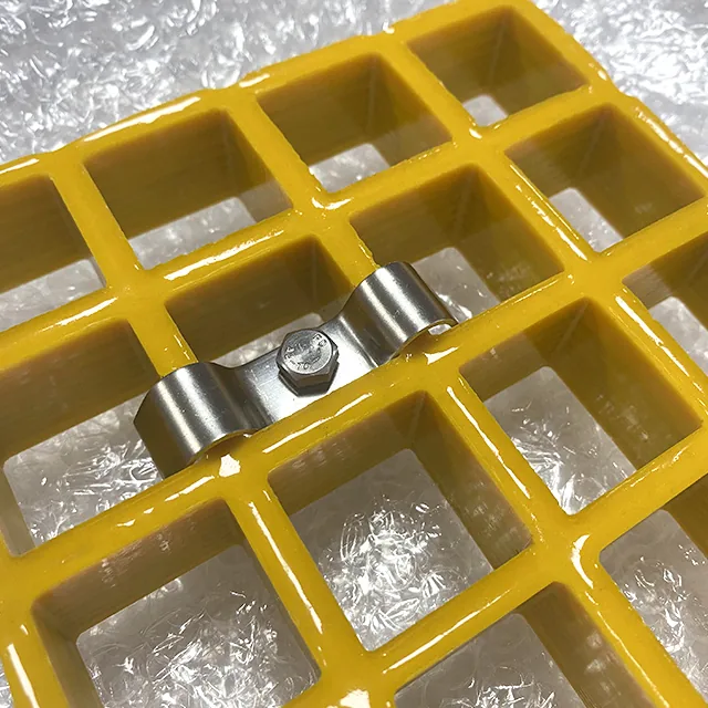
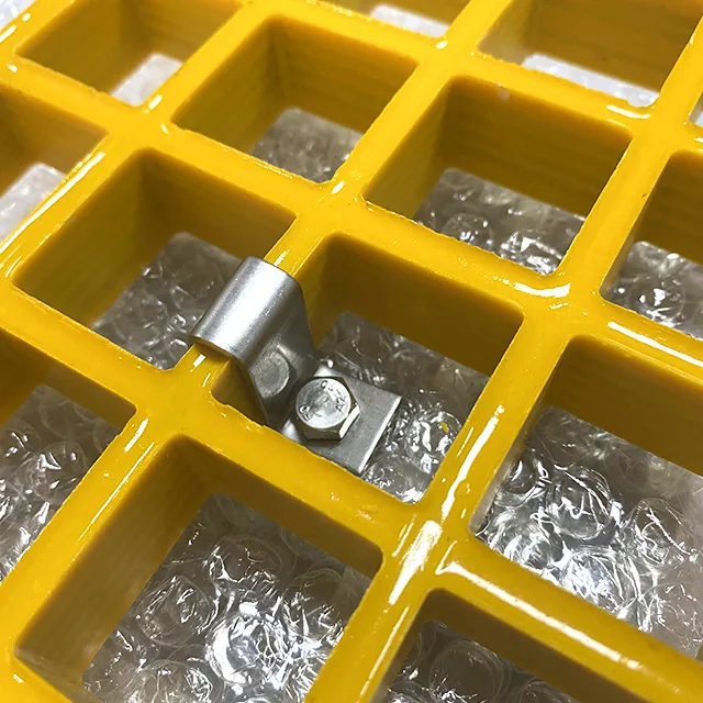
Start with the actual grating. Panel height, bar width, bar pitch, top surface and bar direction determine what a clip can grip. An M clip normally spans two adjacent bars and fastens through the panel to the support below. An L clip bears on a selected bar or edge. A C clip commonly joins adjacent panel edges or controls the step at a joint.
Those descriptions are not fit guarantees. The jaw opening, bolt centre, washer and overall height must match both panel and rail. A clip that looks similar in a photograph can be intended for a different panel height or support shape.
The fixing layout comes from the support drawing. It should show where the panel must be held down, which edge zones require restraint and how removable pieces are released. It should also show whether a clip position is accessible with the actual tool. A fixing detail that cannot be reached during installation or maintenance is not a usable detail.
The M, L and C clips guide explains the families, while outdoor uplift and removable access deals with the project restraints. A clip is a restraint, not a bearing support and not a correction for a rail that sits too low or too high.
The Rail Sets Bearing, Span and Clip Reach
The rail is the line between the panel and the roof. Its position and direction set the bearing. Its spacing sets the clear span. Its profile determines whether the clip can sit flat and whether the bolt can engage safely. A rail can look substantial and still be unsuitable if it is too narrow, too flexible or not part of the array’s structural design.
Put the following on the rail drawing:
- rail section and material;
- direction relative to the walkway;
- spacing between rail edges;
- bearing width under the panel;
- support brackets and their spacing;
- clip positions and bolt access;
- joints, changes of level and walkway turns; and
- any expansion or movement detail.
A 2000 mm walkway piece does not need a 2000 mm unsupported span. Repetitive rail support may produce a conservative structural condition even when the finished piece is long. The reverse is also possible: a short piece can be poorly supported if it rests on only two narrow points. The strip sizing guide explains how finished-piece dimensions and clear spans are kept separate.
Clamping Pressure, Movement and Mixed Materials
The clip has to restrain the panel without crushing the bars or relying on a guess at bolt torque. Excess tightening can indent the composite, crack a bar around a drilled hole or distort a light section. A fixing that is too loose can allow movement, wear and loosening under traffic or vibration.
Use the fastener and clip supplier’s tightening method for the actual assembly. If the project needs a controlled torque, state that requirement and the responsible inspector. We do not publish one torque figure for every panel height, bar section, washer and rail because the combination is not interchangeable.
The support geometry should also allow the expected temperature movement. Long runs, fixed brackets and restrained ends can create a different movement question from short removable strips. The temperature and thermal-movement guide explains the inputs; the fixing detail still has to show how the panel and rail behave together.
When stainless clips meet galvanized or carbon-steel supports, do not assume that both metals remain compatible in every environment. Trapped moisture, salt and coating damage can change the corrosion question. State the material, coating and exposure, and let the responsible designer confirm whether isolation, a different grade or another washer is required.
What the Fixing Drawing Should Show
A usable drawing does not need to show every bolt on a crowded overview. It does need a section and a plan that allow the four layers to be read together. Use one datum and one revision for the panel piece, rail, bracket, roof attachment and removable detail.
The plan should identify each walkway piece, the rail beneath it and the fixing positions. The section should show the panel sitting on the rail, the clip clamping the correct bar, the bolt or fastener below, and the bracket or roof attachment that receives the load. At turns and changes of level, add a second detail; a straight-run section cannot prove that the transition is supported.
For removable sections, show the fasteners that are released and the ones that remain. State whether the piece can be lifted vertically or must slide. If a railing, conduit or module frame blocks the lift path, the section needs to show that too. The maintenance procedure should return the piece to the same orientation and fixing set.
The same drawing should name the responsible party for:
- the array rail and bracket capacity;
- the roof fastener or ballast arrangement;
- waterproofing and any penetration seal;
- installation and tightening;
- inspection after installation; and
- later removal and reinstatement.
If an item is not known, label it “to be confirmed” rather than leaving a blank that can be interpreted as included. This is especially important when a walkway catalogue photo shows a complete system but the quotation covers only grating and clips.
Direct, Raised and Penetrative Are Different Strategies
Competitor installation pages commonly discuss walkways mounted directly on the roof sheet, raised above it, or attached through dedicated supports. Those descriptions are useful, but the physical strategy still has to fit the roof.
Direct or low-profile support can reduce the added height and leverage. It still needs a rail or bearing member, and it may hold water or debris around the support if drainage is not detailed.
Raised support can make cleaning and drainage easier and can align the walkway with a rail system. It creates brackets, higher load eccentricity and more exposed hardware that must be checked.
Penetrative attachment can provide a direct structural connection where the roof detail allows it. The hole, anchor, seal, flashing and reinstatement are all part of the roof scope. A walkway supplier may provide a compatible bracket, but that does not approve the roof penetration.
Non-penetrative attachment can use clamps, ballast or a strut base where roof entry is prohibited. It still needs a load path and uplift resistance. “No penetration” is not the same as “no structural question.”
The roofing and waterproofing interface is an equivalent problem for other grating supports: the fixing and the supporting structure must be designed together. The installation sequence in the solar application guide also shows why roof repair and walkway installation should not be handled as one undifferentiated task.
Protect the Roof Surface, Not Only the Connection
A non-penetrative walkway can still damage the roof if the support rubs the membrane, concentrates load on a small base, traps grit or holds water. The walkway has two physical jobs: it must provide a safe route and protect the roof surface from repeated foot traffic and dropped tools. A clean non-penetrating detail does not automatically provide either protection.
Add these points to the roof interface review:
- whether the walkway or bracket contacts the finished membrane;
- the size, material and condition of any protective pad or base;
- how grit, leaves and cleaning water move away;
- whether the support can abrade the roof under thermal or maintenance movement;
- how the roof is inspected without dismantling the entire route; and
- who repairs the membrane if installation, maintenance or a dropped item damages it.
The roof-system designer should approve the compatible membrane interface. Our factory can show the panel and clip geometry and identify a conflict in the supplied detail. We do not replace a roofing membrane test, a manufacturer’s compatibility statement or the site’s waterproofing inspection.
Uplift and Removable Panels Need Positive Restraint
An exposed rooftop walkway may experience wind or other upward action even when it feels heavy. The project’s roof or structural designer is responsible for determining uplift and where fixings are required. The clip supplier can provide a fitting that resists movement, but cannot infer the wind case from a panel size.
Removable panels add another constraint. They need a repeatable release and refit sequence. Removing a clip to reach a module and leaving it out changes the fixing arrangement. The drawing should identify:
- which pieces are removable;
- which clips or fasteners remain fixed;
- how the piece is lifted without damaging adjacent modules;
- where the removed piece is stored; and
- how its reinstatement is checked.
If every panel is treated as interchangeable, a wrong orientation or missing clip may not be noticed. Use piece IDs and a simple handover record.
Leave the Roof Detail With the Roof Designer
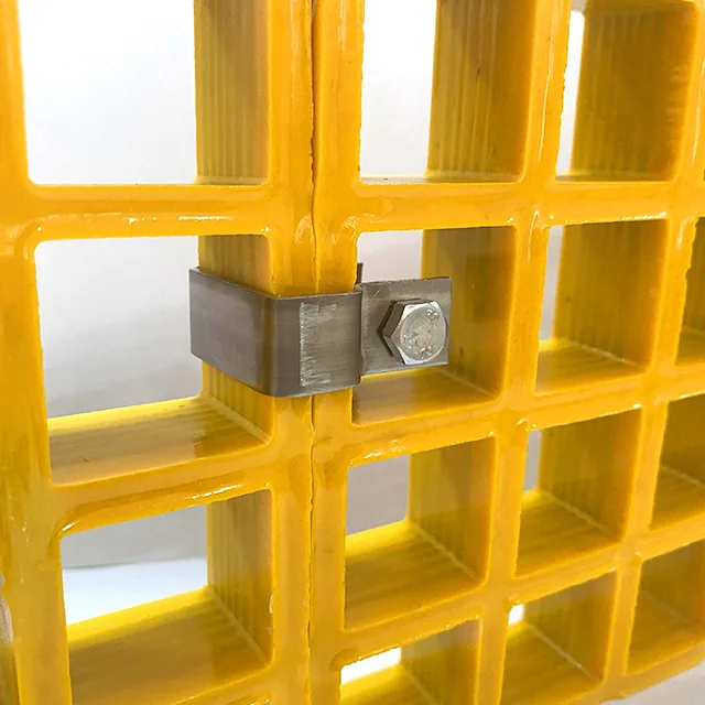
The solar walkway supplier can state the panel and clip scope. It can review whether the proposed rail profile and bracket interface are physically compatible. It should not silently approve a roof anchor, calculate a building load or certify waterproofing unless that work is actually included.
That boundary is useful for procurement. The quotation can list:
- grating pieces;
- grating clips and hardware;
- rail or bracket items offered;
- roof anchors or sealant items offered;
- installation items;
- required structural or waterproofing approval; and
- items excluded or awaiting confirmation.
When an item is not included, leave it visible. A note that says “installation by others” is clearer than a photograph implying that the package includes the entire finished system.
What the Factory Can Confirm
We can confirm the grating construction, finished-piece IDs, edge treatment, clip type and physical fit for the agreed panel and support. We can prepare the quotation with separate lines for panels, fabrication and agreed accessories. We can also identify when the rail, bracket or roof interface is not sufficiently described to release a complete fixing detail.
Our review record follows the same identifiers through the drawing, panel list, clip list, packing and handover. That makes it possible to compare what was designed with what arrived. The factory cannot replace the array-rail or roof engineer, and it does not claim that one clip pattern fits every project.
Manufacturer Review Notes
Senyang’s solar walkway installation guide usefully separates mounting structure, support rail, walkway panel, fastening and inspection, and notes direct and elevated roof arrangements. Power Stone’s FRP walkway system shows the range of rail, L-foot and clamp components that can be integrated with a mounting system. Gratemetal’s solar walkway clamp page distinguishes penetrative and non-penetrative strategies and explains why roof access details vary by project.
Those pages are useful because they show the physical components. Our additional factory view is to prevent the component list from becoming an implied system approval. A matched set of clips is still not a roof design. The final drawing must show the four layers and each responsible party.
Project checklist
What to Send With a Solar Fixing Enquiry
Ten inputs let the supplier quote its scope without implying responsibility for another party's layer.
- Walkway piece schedule — Piece IDs, dimensions, panel type, height, bar pitch, surface and removable sections.
- Grating clips — Type, material, jaw, bolt, washer, intended position and whether clips are in supply scope.
- Rail detail — Profile, dimensions, material, direction, spacing, bearing width and connection to brackets.
- Bracket and elevation — L-foot or bracket type, adjustment, route level, cross-slope and expansion or movement.
- Roof interface — Existing roof build-up, support location and whether penetration is allowed.
- Waterproofing — Approved seal, flashing, drainage path, installer and inspection responsibility.
- Uplift — Wind condition, lifting concern, edge zones and positive restraint requirement.
- Installation sequence — Access direction, removable pieces, bolt reach, tools and safe handling.
- Supply boundary — Which party supplies panels, clips, bolts, rails, brackets, anchors, sealant and installation.
- Evidence — Drawing revision, structural check, roof approval, material records and handover checklist.
Four boundaries
What a Grating Clip Cannot Prove
A good fit is necessary but does not approve the rail, roof or installed system.

A panel clip is not a roof fixing
It holds the grating to the rail; it does not approve the rail, bracket or roof.
A standard pitch is not a clip rule
Fixing positions follow the support layout, edge zones and project restraint requirement.
A joint clip is not bearing
C clips can join edges without supplying support underneath a panel joint.
The installed set must match the drawing
Missing clips, substituted hardware or altered removable pieces change the verified arrangement.
Request a review
Send the Section Through Panel, Clip, Rail and Roof
Mark what is supplied, installed, sealed and structurally approved at each layer.
- Attach a section through all four fixing layers
- Mark penetrative or non-penetrative scope
- State who seals and approves the roof
Solar Walkway Fixing Questions
What are the main parts of an FRP solar walkway fixing?
How many clips does a solar walkway need?
Can a standard M clip be used on every solar rail?
Is a non-penetrative fixing automatically safer?
Does the grating supplier approve the roof attachment?
What should be recorded for removable walkway panels?
This content was prepared and reviewed by Dengtai Industry’s technical and production team using the project conditions, available product data and applicable documents. Limits that require design, testing or approval are identified in the content. Content last checked: