PV maintenance strip review
FRP Solar Walkway Strips: Width, Support and Cutting Yield
Start with the maintenance route and the available gap between PV rows. Then match the rail layout, bar direction, finished-piece weight, cut allowance and clip positions before treating any strip size as a quotation-ready configuration.
Prepared by
Dengtai Industry
Published
·
Reviewed

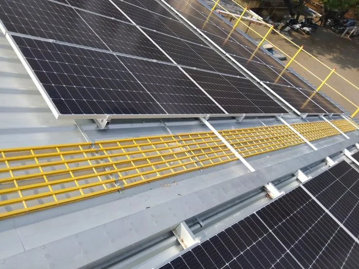
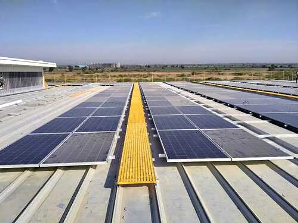
Strip pieces follow the available route between PV rows. The supplier still needs the rail and support information. Photo: Dengtai Industry.
Strip vocabulary
Six Dimensions That Define a Solar Walkway Strip
Route width and clear span describe different things, just as piece area and sheet consumption do.
- Solar walkway strip
- A narrow finished grating piece used as part of a photovoltaic maintenance route. It is a cut-to-size product, not a standard panel simply renamed by width.
- Route width
- The usable walking width after considering module rows, rails, guardrails, edge clearance and the project's access requirements. It is not set by a catalogue size.
- Strip length
- The finished piece length along the route. It is separate from the clear span between supports and from the full panel length before cutting.
- Clear span
- The unsupported distance between the edges of supports beneath the strip. A long finished piece can still have a short clear span if properly supported.
- Bearing width
- The width of contact between the grating and rail. A clip can hold the strip down without providing enough bearing or support.
- Bar direction
- The direction in which the grating structure carries its design load. Molded and pultruded products behave differently, and pultruded strips are especially directional.
- Cutting yield
- The usable finished-piece area obtained from a full panel after cut kerf, edge trim, defects and offcuts are accounted for. It is not the same as sum of piece areas.
- Handling limit
- The maximum finished-piece size and mass that the installation team can carry, lift and position safely along the actual roof route.
When this review applies
When a Solar Walkway Needs a Purpose-Made Strip
Narrow routes and fixed module spacing usually require a piece list rather than an off-the-shelf panel.
Specify this if…
- The walkway runs in a narrow space between PV module rows or along an array edge.
- The panel can be cut in the factory with a repeatable piece list.
- The rail layout, clear span and fixing locations can be shown.
- The installation team has a defined manual-carrying or lifting limit.
Look elsewhere if…
- A strip width is being chosen from a catalogue without the route and rail layout.
- The finished length is being treated as the clear span.
- The lowest panel-area rate is being compared without the nesting loss.
- Roof attachment, waterproofing or structural approval is being assumed from the grating quote.
Sizing logic
What Sets the Strip and What It Cannot Prove
Every dimension answers a different project question.
| Decision | What sets it | What it does not establish |
|---|---|---|
| Strip width | Access task, available gap, guarding, rail position and edge clearance | A universal code width or that the route is safe |
| Strip length | Route module, panel joints, handling and cut plan | The clear span between rails |
| Thickness | Product structure, support, load and deflection checked together | A stand-alone load class |
| Bar direction | The grating construction and the direction of its design load path | That either orientation has the same capacity |
| Nesting plan | Full sheet width, strip widths, actual kerf, trim and defects | That piece area is the same as material consumed |
Quotation fields
Solar Strip RFQ and Drawing Inputs
The information that turns a candidate width into a fabricable and comparable piece.
| RFQ field | Information required | Why it changes the strip |
|---|---|---|
| Route and task | Array layout, maintenance activity, carried tools and access points | Determines the usable route and handling strategy |
| Support drawing | Rail location, profile, bearing width, spacing and direction | Sets the clear span and panel-direction check |
| Finished strip | Width, length, quantity, panel construction and bar direction | Defines the actual cut piece rather than a full sheet |
| Weight limit | Maximum piece mass and method for lifting or carrying to the roof | Can require joints or shorter finished pieces |
| Cutting plan | Full panel format, strip grouping, kerf, trim and usable offcut | Changes material yield and quotation comparison |
| Interfaces | Clips, joints, openings, edge treatment and module/rail clearances | Determines fabrication and installation scope |
Layout sequence
From Maintenance Route to Cutting Plan
Draw the route first, add the supports, size the pieces, then test the nesting layout.
Mark the start, end, width constraints, turns, module rows and access points on the array layout.
Add rail direction, spacing, bearing width, transitions and every intended clip position.
Give each strip a width, length, quantity, surface, bar direction, openings and edge treatment.
Compare each piece with the agreed manual-carry or lifting limit and split pieces where necessary.
Fit strip-width rows plus measured cut allowance and trim into the usable full-panel dimensions.
Carry the drawing revision and piece ID through cutting, inspection, packing and installation.
A Solar Walkway Strip Is a Finished Piece, Not a Product Category
“Solar walkway strip” usually describes the finished shape needed between photovoltaic module rows. It may be narrow, long and supplied in repeated pieces, but there is no universal strip width or load class attached to that phrase. The finished piece comes from a route, a support plan and a product configuration.
That distinction prevents a common quotation error. A buyer asks for a desired width, receives a panel-area rate and later discovers that the rail spacing, bar direction, clip reach or piece weight has not been checked. The width may be fabricable while the complete walkway proposal is still incomplete.
This guide approaches the strip as our factory would review a production order. We start with the route drawing and the full panel format, then connect the finished-piece list, cutting yield, edge treatment and handling record. The supporting roof and array structure remain a separate engineering scope unless a written quotation says otherwise.
Route Width Comes Before Catalogue Width
The useful first dimension is the walking route, not the strip. Mark where the maintenance team enters the array, how far it travels, what tools or cleaning equipment it carries, and how it reaches the modules. Then mark the available gap between module rows, rails, cables, guardrails and roof features.
Several project inputs can constrain the route:
- the need to pass a person, tools or a removable section;
- clearances from module glass, frames and electrical equipment;
- transitions at array ends, walkway turns and roof access points;
- guardrails, fall protection and edge restrictions;
- space needed to lift and place a replacement strip; and
- the carrying route from the roof access point to the installation area.
A strip that fits between two module rows can still be unsuitable if there is no safe transfer width or if it cannot be carried into position. The broader solar walkway guide explains the application context; this page focuses on the finished strip.
The Rail Layout Determines the Actual Structural Question
The strip rests on rails, tracks or dedicated supports. Put those supports on the same drawing. Mark their direction, profile, spacing, bearing width and intended clip positions. The distance between the support edges is the clear span. The strip’s finished length is a separate dimension.
A 2000 mm piece may cross several rails at 500 mm centres, or it may rest near its ends with a much longer unsupported centre. The same piece length can therefore describe a conservative layout or a poor one. Load, deflection and support spacing have to be checked for the actual arrangement.
Bar direction matters most visibly in pultruded grating, where parallel bearing bars carry the main load along one direction. A pultruded strip supplied with the wrong bar orientation cannot be corrected by adding clips. Molded grating carries load through an integral mesh, but its structure and support basis still have to match the selected panel. The pultruded grating guide and load-span guidance explain why thickness alone is not a capacity.

Width, Length and Weight Have to Work Together
A narrow strip can be long enough to become heavy and awkward. For a 25 mm molded panel with a reference mass of 12.5 kg/m², a 400 × 2000 mm piece weighs about 10 kg before clips, packing and any surface treatment. The same product cut 300 × 3000 mm weighs about 11.25 kg. Length and width both affect handling.
Use the site’s actual carrying method. A two-person carry on a clear roof is different from a single-person replacement route beside solar modules. Stairs, hatches, roof edges and wind can make a mathematically manageable piece difficult to install. If the piece is too large, split the run into identified joints rather than asking the installer to force it into place.
The finished-piece list should state width, length, quantity, thickness or bar profile, mesh or pitch, resin, surface, colour, bar direction, openings and edge treatment. The same list becomes the cutting instruction and packing schedule.
The solar walkway strip cut-list and yield template carries that width decision into full-panel nesting, remnant control, piece IDs and labelled packing.
A Rough Width Example, Not a Route Rule
Consider a demonstration layout with three 400 mm strips across a nominal 1220 mm panel. The three nominal widths total 1200 mm. That leaves only 20 mm for every cut gap, edge trim and any unusable zone. Whether the job actually fits depends on the measured allowance from the cutting method and the finished edge requirement.
The factory check is therefore:
number of strip rows × strip width + cut allowance + edge trim + unusable allowance ≤ usable panel width
This check is more useful than looking only at 1200 mm of finished area. The remaining full-panel area may also be unusable if its width or bar orientation does not suit another piece. The same principle applies along the panel length: the number of finished lengths has to fit the usable length after trim and defects.
We do not publish one universal kerf or nesting percentage. Cutting equipment, edge finishing, defect allowance and the way strips are grouped all affect the result. Give us the full piece list and the acceptable full-panel formats, and the cut plan can be checked against the order.
For the molded configurations shown in our product range, the normal full-panel inputs include 1000 × 4000 mm and 1220 × 3660 mm. Other formats depend on the mold. These dimensions are panel inputs, not automatically the best solar-strip layout. The nesting check still has to show how each width row and finished length uses the selected sheet.
Cutting Yield and Price Are Not the Same as Piece Area
A strip quote can use:
- the sum of finished-piece areas;
- the full-panel area consumed by the nesting plan;
- a fixed fabrication charge;
- or a combination of these bases.
Those methods are not automatically equivalent. A 400 × 2000 mm piece has 0.8 m² of finished area. Three such strips have 2.4 m², but the material consumed may be more because the cut plan uses a particular full panel and leaves offcuts. Before comparing suppliers, ask whether the quotation includes nesting loss, cut-edge treatment, piece marks, clips and packing on the same line.
Our factory view is simple: show the finished area and the consumed material basis separately. That lets the buyer see whether a lower piece-area rate comes from a more efficient layout or simply from excluding the offcut. The cut-to-size guide shows how to prepare the underlying piece list.
Surface, Resin and UV Are Separate From Strip Size
A yellow strip is easier to see against dark modules and roof surfaces, but colour is not a UV certificate. A grit surface can improve grip under wet or dusty conditions, but it is not automatically a tested slip class. Resin selection follows the exposure: an ordinary isophthalic polyester starting point, a vinyl ester direction for stronger chemical or coastal service, or another resin only after the duty is stated.
The strip also needs a defined top face when one side has a different surface. Mark that orientation on the drawing and packing. A reversible piece that is installed upside down may fit but fail the intended walking surface or protective finish.
Resin, pigment and surface protection influence how the panel ages outdoors. The resin selection guide and UV and colour evidence guide set out the separate questions. None of those choices removes the need to check support and fixing.
What a Factory Cutting Plan Can Control
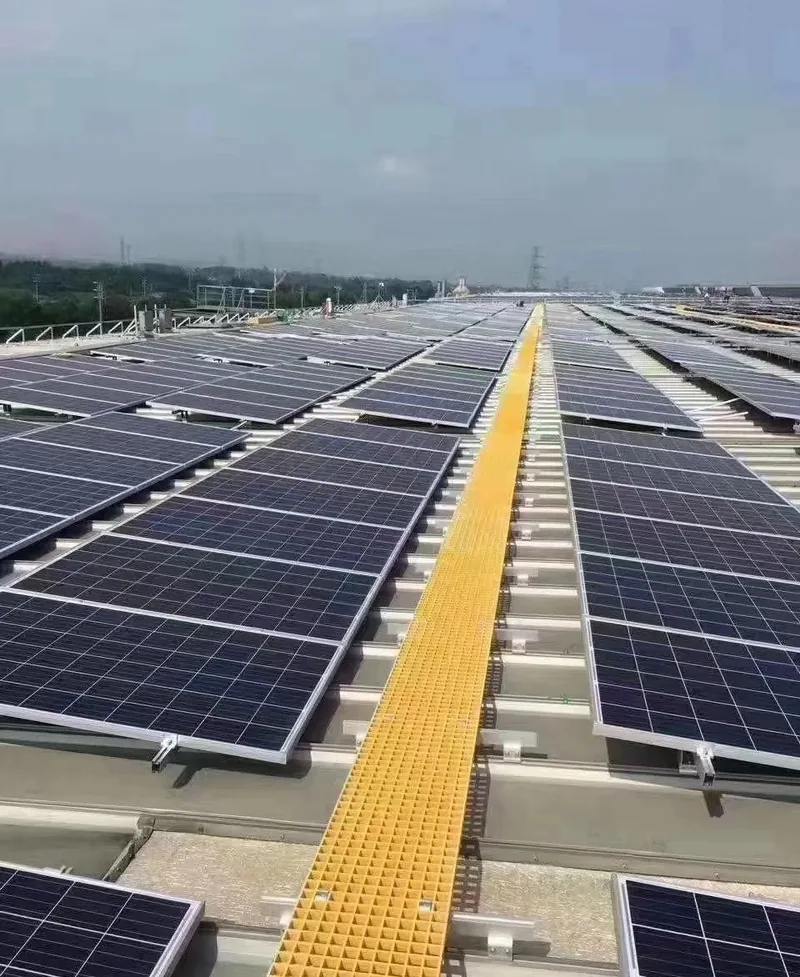
Factory cutting allows the full-panel format, strip widths, lengths, openings and edge treatment to be reviewed together. We can carry piece IDs from the approved cut list to inspection and packing. A checked first piece or dimensional record can reduce the chance that repeated strips vary in width or orientation.
The factory can control the cut plan and the product it supplies. It cannot approve the roof load, the array-rail capacity, the fall-protection system or the installer’s safe carrying route. Those responsibilities stay with the project unless they are expressly included in a written scope.
For repeat strips, provide:
- a drawing revision;
- the full panel format to be used;
- one row for each finished strip size;
- top-face and bar-direction marks;
- openings and edge treatment;
- the permitted nesting or offcut rule; and
- packing and identification requirements.
That information lets the factory and the buyer talk about the same finished pieces instead of a general “solar grating” rate.
What One First-Party Solar Strip Order Shows
Our existing solar walkway record includes an Indonesia shipment of 25 mm molded grating with a 38 × 38 mm mesh, cut to 400 × 2000 mm, in yellow with a grit surface. The panels were made in unsaturated polyester for an ordinary environment, laid on the customer’s existing track supports and connected with M clips.
This is useful first-party evidence because the record connects a finished strip size to a real panel configuration, surface, fabrication route and fixing family. It also shows why the strip cannot be specified from width alone: the rail spacing, clear span, load and deflection limit were not part of the order record available here.
We treat the example as a production precedent, not a design template. It does not prove that another 400 × 2000 mm strip can span the same distance, fit another rail, or carry the same maintenance case. A new project still needs its own route drawing, rail layout, load and evidence requirement.

Manufacturer Review Notes
The useful competitor pages reviewed for this guide take different approaches. DONGFU’s solar PV walkway page connects roof capacity, rail spacing, weather and manual handling to the panel choice. Fibergrate’s rooftop case study documents a real route with twenty 3 × 10 ft molded panels, selected with removable access and a grit surface in mind. Fasten Solar’s walkway product page shows the range of available panel sizes and surfaces.
Those are useful prompts, not data to copy. A 3 × 10 ft piece from another project is not a handling limit for this roof. A catalogue range does not prove the clear span, and a generic grit surface is not a project test result. Our own contribution is to connect the strip schedule to the factory cut plan and expose the yield calculation. The result is a production-ready strip list rather than a page that stops at “lightweight and corrosion-resistant.”
Our Factory Review Boundary
We can review the grating construction, full-panel format, strip width and length, nesting loss, bar direction, surface, edge treatment, piece marking and agreed clips. We can identify an incomplete drawing and return it for the missing route or support data. We do not invent a safe walkway width, approve array-rail capacity, design the roof attachment, certify fall protection or represent a catalogue size as a structural approval.
The best enquiry is a small package: the array drawing, rail detail, finished-piece list and the site’s handling limit. With that, the factory can prepare a clear strip quotation and show which parts remain with the roof or structural designer.
Project checklist
What to Send With a Solar Strip Enquiry
Ten inputs cover the route, structure, fabrication and delivery scope.
- Array and route drawing — Module rows, access points, turns, walkway width, edges, guardrails and nearby equipment.
- Rail and support layout — Rail profile, direction, spacing, bearing width, brackets and intended fixing points.
- Finished-piece list — Strip width, length, quantity, bar direction, surface, colour and edge treatment.
- Panel construction — Molded or pultruded format, full-panel size, mesh or bar spacing, depth and resin direction.
- Handling limit — Maximum piece mass and carrying or lifting method from delivery point to the array.
- Cutting allowance — Any measured kerf, trim, defect allowance and preferred full-panel format.
- Fixings — Clip type, material, fixing positions and the support detail the clips engage.
- Load and deflection — Pedestrian or maintenance load, concentrated load, clear span and permitted deflection.
- Evidence — Any project requirement for dimensions, materials, load, slip, colour or inspection records.
- Delivery — Quantity, destination, packing requirement, piece marks and required date.
Four boundaries
What a Strip Drawing Still Cannot Prove
The drawing coordinates fabrication; it does not replace structural, roof or safety approval.

Piece area is not sheet yield
A group of narrow strips can consume more full-panel area than the sum of finished-piece areas suggests.
Finished length is not clear span
Rail positions and bearing determine the structural question beneath the strip.
A catalogue range is not a route approval
Width, use, guarding and access are project conditions.
One mark should follow the piece
The same ID should appear on the drawing, cut list, inspection record and packing.
Request a review
Send the PV Route, Rail Drawing and Piece List
A measured route and support layout are more useful than a request for one strip width.
- Attach the route and rail drawing
- Give the finished-piece list and handling limit
- State whether cut yield or installed area is quoted
Solar Walkway Strip Sizing Questions
What is the standard width of an FRP solar walkway strip?
Can a strip be 400 mm wide?
Is a 2000 mm strip a 2000 mm span?
Why can a narrow strip cost more than its finished area suggests?
Should the strip run along or across the rails?
Can the factory supply the roof brackets too?
This content was prepared and reviewed by Dengtai Industry’s technical and production team using the project conditions, available product data and applicable documents. Limits that require design, testing or approval are identified in the content. Content last checked: