Machine maintenance access
Grating Around Machines: Cutouts, Removable Panels and Edges
Start with the machine service action and movement envelope. Then separate fixed grating, permanent penetrations, removable panels and covers, while resolving support, edges, release hardware, guards and reinstatement.
Prepared by
Dengtai Industry
Published
·
Reviewed

The platform is part of the access system around the equipment. Machine guarding and isolation remain distinct controls. Photo: Dengtai Industry.
Access vocabulary
Machine Platform Opening and Removable Panel Terms
- Machine platform grating
- A grating walking surface around installed equipment that supports access for operation, inspection, cleaning, maintenance or removal activities.
- Permanent cutout
- An opening left for a pipe, cable, fixed service or permanently installed component. It normally has no routine cover release, but still needs edge treatment and support around interrupted grating bars.
- Removable maintenance panel
- A designed platform piece that is released, lifted, stored and reinstated to expose a service area or allow equipment movement.
- Cover piece
- A grating, plate or assembly placed over an opening. It needs its own bearing, restraint, handling, position and reinstatement.
- Equipment envelope
- The installed equipment footprint plus the movement required to operate, inspect, lift, withdraw or replace it.
- Service clearance
- Space for hands, tools, temporary parts, inspection and protective equipment during the actual task.
- Closed-state restraint
- The clips, bolts, hinges or other devices that keep a panel or cover seated when the machine platform is in normal service.
- Open-state protection
- The barrier, cover, guard, procedure or other project control used while the panel is removed or moved aside.
Start with the task
When Machine Grating Needs a Purpose-Made Panel Schedule
Specify this if…
- The installed machine and the service action can be shown.
- The movement envelope for a part and the worker's tool clearance are known.
- Fixed cutouts, removable panels and covers can be distinguished.
- Support, bearing and clipping around the opening can be drawn.
- Temporary equipment feet, jacks, hoists, carts and stored parts can be identified.
- Vibration, equipment movement and removal frequency can be stated.
- The open-state protection and machine isolation method have an owner.
- Finished-piece mass, release hardware and reinstatement can be defined.
Look elsewhere if…
- An opening is dimensioned from a pipe diameter alone.
- A panel is called removable because unspecified clips are available.
- The worker must step or reach through an uncontrolled opening.
- Machine guarding, lockout or restart responsibilities are unresolved.
- The panel layout is expected to replace the equipment manufacturer's maintenance procedure.
- A hatch created after fabrication has no support or edge detail.
Opening boundary
Fixed Cutouts, Removable Panels and Covers Serve Different Tasks
| Access type | System responsibility | What the grating quotation can supply |
|---|---|---|
| Permanent pipe or cable penetration | Opening location, equipment envelope, service gap and support around interrupted bars | A fabricated opening with agreed edge and piece identification |
| Removable maintenance panel | Release, lift path, storage, reinstatement and open-state control | The panel, agreed hardware and handling detail when included |
| Lift-out inspection cover | Opening size, cover mass, handles, bearing seat and refitting | A matched cover piece and agreed restraint, not the entire operating procedure |
| Hinged cover | Hinge, stay-open condition, clear swing and closed latch | A compatible panel when the full hinge and safety design is specified |
| Fixed grating panel | Permanent support, clipping, route continuity and inspection | Full or cut panel manufactured to the approved layout |
| Machine guard or barrier | Moving-part, hot-surface, pressure or other machine hazard | Nothing unless a separately engineered guard system is in the agreed scope |
Product route
Machine-Platform Access Directions
Molded platform pieces
Best where the exact panel row, cutouts and working area can be defined and the supported span matches the selected construction.
Pultruded platform grating
Directional bearing bars suit a defined support layout, but the bar direction and end bearing must match the machine platform drawing.
Factory-cut opening pieces
Openings, notches, edge sealing and piece marks are fabricated from a controlled schedule rather than improvised on site.
Removable covers and panels
A defined piece with handles or lift points, release hardware, bearing seat, storage method and reinstatement sequence.
Mixed fixed and removable layout
Separate the ordinary walking area from machine-service access while keeping one frame and drawing revision.
Schedule fields
Fields for a Machine Grating Panel Schedule
| Schedule field | What to enter | Why it changes fabrication or access |
|---|---|---|
| Machine ID | Equipment name, tag and drawing reference | Prevents the opening from being detached from its task |
| Maintenance action | Reach, inspect, operate, lift, withdraw or clean | Defines the opening and clearance |
| Equipment envelope | Installed footprint plus movement path and temporary parts | Sets the minimum practical opening |
| Opening type | Permanent cutout, removable panel, lift-out cover or hinged cover | Determines restraint, handling and edge detail |
| Opening datum | X/Y references, shape, tolerance and service gap | Makes the fabrication and site check repeatable |
| Support and frame | Bearing edges, interrupted bars, added support and frame condition | Prevents an unsupported opening boundary |
| Mechanical duty | Equipment-foot, jack, hoist, tool-cart and stored-part loads; contact area and location | Separates normal access from temporary maintenance loads between supports |
| Movement and frequency | Vibration, machine movement, removal frequency and expected fixing disturbance | Guides release hardware, positive restraint and the post-refit check |
| Removal and handling | Piece mass, handle, lift direction, storage and reinstatement | Shows whether the access action is practical |
| Open-state control | Temporary guard, barrier, cover and responsible owner | Keeps the open condition separate from the grating piece |
| Machine safety | Isolation, moving-part guard, hot surface and restart reference | Prevents a utility panel from being treated as machine protection |
| Identification | Unique panel ID, location, revision and packing mark | Ensures the correct piece returns to the correct opening |
Worked example
An Illustrative Machine Access Schedule
| Illustrative item | Description | Why the line exists |
|---|---|---|
| MP-01 | Fixed platform panel around equipment | Continuous walking surface supported by the agreed frame |
| MP-02 | Permanent pipe penetration in a fixed panel | Separate edge and remaining-bar review |
| MP-03 | Removable pump-service panel with two handles | Defined lift direction and stored position |
| MP-04 | Lift-out cover for an inspection point | Bearing seat, restrained closed state and reinstatement |
| MP-05 | Edge trim and sealed cut faces | Fabrication scope tied to the approved drawing |
| MP-06 | Temporary opening barrier, owner and procedure | A control separate from the grating order |
Seven-step method
How to Plan Grating Around a Machine
Show the equipment in its installed state and the approach, inspection or removal action.
Include the worker, tools, temporary parts and movement path for the component.
Separate permanent penetration, removable panel, lift-out cover and hinged cover.
Mark interrupted bars, frame bearing, added support and the fixed panel boundaries.
Give the piece an ID, mass, lift direction, storage method and closed restraint.
Name the temporary barrier, cover or procedure and assign its owner.
Carry dimensions, openings, edges, IDs and reinstatement checks into fabrication and packing.
A machine platform opening should start with the maintenance action, not the diameter of the pipe or the available saw path. Record what a person must reach or move, which direction the component travels and what space is needed for hands, tools and temporary parts. Then decide whether the platform needs a permanent penetration, removable panel, lift-out cover, hinged cover or a combination.
This page is narrower than the general platform cutout guide. The focus is equipment access: the machine envelope, open and closed states, and the boundary between the grating supply and machine safety. The temporary access panel guide explains the reusable restraint and removal cycle in more depth.

Draw the Machine Envelope Before the Opening
The installed equipment footprint is only the first outline. A pump may need to move along a guide rail. A motor may be lifted vertically. A valve stem or actuator may require tool rotation. Hoses, temporary supports and removed fasteners all occupy working space.
Draw the installed position and the service position together. Then mark the worker’s approach, hands, tools and any carried part. A large hole that exposes the top of a component can still be the wrong shape if the component must move sideways.
The maintenance task should have a name and owner. “Machine access” is too broad to determine whether the piece should be a fixed cutout, a full panel, a cover or an opening in a removable strip. An equipment ID and drawing revision keep the opening attached to that action.
Record Maintenance Loads and Vibration, Not Only Foot Traffic
A platform around equipment is loaded differently during service. A motor foot, temporary jack, pump skid, hoist reaction, tool cart or stored component can concentrate load at one location. Dividing a component’s total mass across the platform is not a substitute for the contact load at that point.
| Service condition | Record | Why it changes the platform |
|---|---|---|
| Equipment foot or pad | Load, contact footprint, location relative to bars and supports, plus duration | A local concentrated load can govern when the uniform walking load does not. |
| Temporary jack or stand | Reaction, base size, bearing location, temporary support and release sequence | The maintenance method may create a smaller and more severe contact area than the installed machine. |
| Hoist or suspended component | Vertical and horizontal reaction, attachment point, swing path and temporary storage | Lifting can load adjacent panels or require space that is not part of the opening footprint. |
| Tool cart or stored part | Wheel or foot loads, travel route, parking position and duration | A moving cart can place load between the supports assumed for normal access. |
| Vibration or machine movement | Source, operating condition, project criterion and effect on clips, bolts, hinges and seats | The fixing method and inspection basis must suit the expected movement instead of relying on a generic clip. |
| Repeated removal | Frequency, tool access, release time, handling route and post-refit check | High-cycle access may justify smaller pieces, retained fasteners, lifting aids and a shorter inspection route. |
Where vibration or equipment movement is expected, the fixing design still has to come from the project. A lock nut, washer or thread-locking product is not selected from a catalogue sentence alone; it must suit the fastener, hole, support, environment and release requirement. The handover should identify the installed fixing arrangement and the checks performed after a panel is returned. A panel that repeatedly loosens needs a design review, not an endless tightening cycle.
Our factory quotation review does not average these maintenance actions across the whole platform. We ask for the load source and location so the affected panel, interrupted bar and nearby support can be identified. That makes the removable piece a controlled service interface rather than a loose rectangle over an opening.
Fixed Cutout, Removable Panel and Cover Are Different Products
A permanent cutout for a pipe is normally surrounded by fixed grating. The opening should show the pipe location, service gap, interrupted bars and added support. It does not need a release mechanism simply because an object passes through it.
A removable maintenance panel is a walking-surface piece that leaves the platform to expose a larger service area. Its design includes the full piece, release hardware, handle or lift point, mass, storage position and reinstatement. The open state is an operating condition, not a hidden consequence of removing the panel.
A lift-out inspection cover closes a smaller opening. It needs a bearing seat, a defined lifting grip and a clear closed state. If the cover is hinged, the hinge and stay-open condition become part of the supply and safety review. None of these types is interchangeable just because they cover the same opening size.
Dongfu’s industrial platform page usefully distinguishes permanent fixed areas from panels intended for maintenance removal. Its steel-grating fixing language is not copied into FRP practice, but the planning principle is relevant: the fixing method must follow whether the panel is permanent or removable.
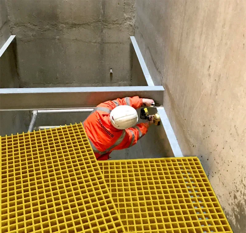
Every Opening Interrupts the Support and Walking Edge
The platform plan should show the frame or bearing surfaces around the opening. If the spacing was based on uninterrupted panels, a cutout can leave a boundary without a bearer. Cutting a larger opening also removes walking area and may force a transition or edge guard.
For molded grating, the cut interrupts bars in both directions. For pultruded grating, bearing-bar direction and end support determine the structural consequence. The platform cutout guide explains those mechanisms. This page adds the machine-access reason for the cut and the open and closed states.
Cut edges and drilled surfaces should be treated according to the agreed finish. A neat edge is not proof that interrupted-bar support was reviewed. The schedule needs one piece ID for fixed panels, removable panels, covers and transitions so that a shaped opening cannot turn into an unnamed remnant.
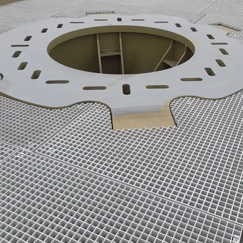
Keep Machine Guarding and Isolation Outside the Grating Order
Removing a panel can expose moving machinery, hot surfaces, pressure, electrical energy or falling material. The grating is a walking surface. It is not automatically a machine guard, an energy-isolation procedure or a permit for entry.
The project should state who authorises removal and what happens before, during and after access. Machine isolation, lockout/tagout, inspection, restart and the temporary guarding of the opening are separate safety controls. If a guard must be supplied with the grating, it needs a designed interface rather than a note saying “add safety guard”.
This boundary is also useful to the supplier. We can manufacture the access panel and agreed hardware to a drawing. We should not infer that a lifting hole, clip or panel automatically satisfies the equipment manufacturer’s requirements. The temporary access panel page explains a similar closed, open and reinstated control cycle.
Check the Removal Path and Reinstatement Before Fabrication
The panel must be light and shaped for its real lifting route. Check handles, grip points, neighbouring beams and the space where the panel is stored while it is removed. A large one-piece panel may be convenient on the drawing and impractical in the machine aisle.
Reinstatement needs marks and a seat check. The piece should carry an ID, the opening should carry a matching ID, and the clips or fasteners should be identifiable. The final handover should include the removal direction and what needs to be inspected when the panel is returned.
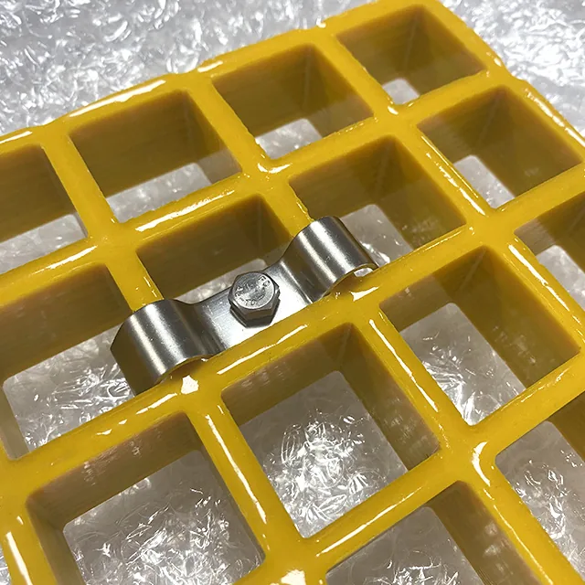
What the Strongest Peer Content Adds
The best platform peers treat access as a complete system. A manufacturer’s fixing guidance can distinguish permanent and removable zones. A maintenance-platform case can show supports, railing and access sequence around the equipment. Generic product pages often show the grating and mention “easy access”, but do not show the piece schedule or open condition.
We combine those useful ideas with our factory-facing schedule. Each line names a machine, opening type, support, finished piece and reinstatement. This makes the order buildable and prevents “removable panel” from meaning an unassigned loose rectangle.
It also shows where customers need project engineering: machine safeguarding, structural supports, fall protection and the operating procedure. A panel can be well made and still not be the right control for a machine hazard.
Our Factory View: One Piece, One ID, One Location
Our factory review needs the current platform and machine drawing, the opening schedule and the exact removal method. We can review whether the panel construction is fabricable and identify supports and edges that the drawing has not resolved. We cannot approve an unstated machine safety system or invent the equipment envelope.
The approved schedule lets us cut, finish, mark and pack the fixed and removable pieces together. We also separate release hardware from ordinary hold-down clips in the packing logic and use the panel ID to keep matching handles, covers and markings with the correct opening. That traceability is especially important when similar panels differ by one opening, support detail or release method. The packing list should make the installation set obvious before the platform is dismantled.
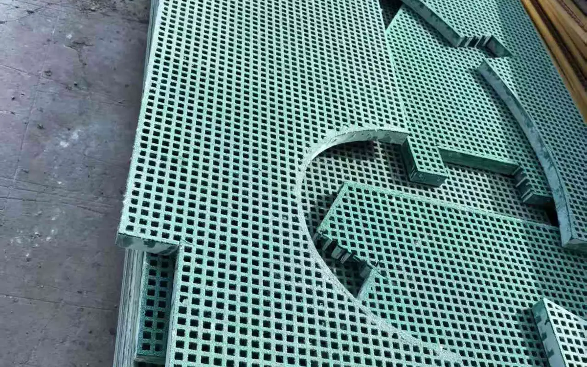
Before fabrication
Machine Platform Grating Checklist
- Machine and task identified — The equipment ID and exact maintenance action are shown.
- Movement envelope drawn — Installed and removal positions, tools and temporary parts are included.
- Opening type chosen — Fixed penetration, removable panel and cover are not mixed.
- Support around opening resolved — Bearing and interrupted-bar treatment are defined.
- Edge treatment specified — Cut edges, openings and exposed surfaces have an agreed finish.
- Removal path checked — Mass, handle, lift direction, adjacent structures and storage are practical.
- Closed restraint defined — Clip, bolt, hinge or latch function is identified.
- Temporary service loads recorded — Equipment feet, jacks, hoists, carts and stored parts are located against supports.
- Movement and refit checks defined — Vibration, removal frequency and post-refit fastener checks are assigned.
- Open state controlled — The temporary protection and responsible owner are recorded.
- Machine safety boundary stated — Isolation, guarding and restart remain separate from the grating.
- Piece IDs carried through — Each fixed, removable and cover piece is marked through production and delivery.
System boundary
What the Grating Panel Does Not Control

The platform is not the machine guard
Removing a panel can expose moving parts, heat, pressure or stored energy. Machine guarding and isolation remain separate controls.
The panel is not the operating procedure
A liftable piece does not define who may enter, how the machine is isolated or how the area is made safe.
A permanent cutout needs support even without a cover
Interrupted grating bars, pipe clearances and edge treatment remain fabrication and engineering questions.
A removable panel needs a repeatable return
Position marks, hardware, seating and inspection are required for correct reinstatement.
Plan the maintenance opening
Send the Machine and Platform Drawings
- Molded and pultruded grating produced in house
- Full panels or factory cut-to-size pieces
- No fixed minimum order quantity
Machine Platform Grating and Removable Panel Questions
What is machine platform grating?
Should the panel around a machine be removable?
Does a grating panel protect workers from moving machine parts?
How large should an equipment cutout be?
Can a cutout be added after the grating is delivered?
Who provides the temporary cover while a panel is removed?
What loads besides foot traffic matter around a machine?
This content was prepared and reviewed by Dengtai Industry’s technical and production team using the project conditions, available product data and applicable documents. Limits that require design, testing or approval are identified in the content. Content last checked: