Load-table selection guide
Selecting the Correct Molded FRP Grating Load Table
The right row is not the thickest one or the closest-looking number. It is the row whose construction, support arrangement, span definition, load pattern, deflection basis and service conditions match the installed panel.
Prepared by
Dengtai Industry
Published
·
Reviewed

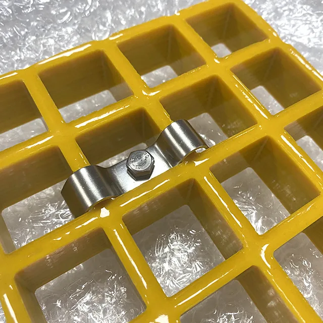
A physical sample proves the visible construction. The load table still has to match the support, span and load case. Photo: Dengtai Industry.
Field definitions
What Makes a Molded Grating Load-Table Row Applicable
These terms prevent a copied number from arriving without its design conditions.
- Load-table row
- One set of structural values for a defined construction and stated conditions. It is not interchangeable with another row merely because the depth or panel appearance is similar.
- Construction
- Molded or pultruded, depth, bar geometry, pitch, reinforcement and resin. Mini mesh, rectangular mesh and heavy-duty products can be separate structures.
- Span
- The dimension used by a particular table. It may describe clear span, support centre distance or another stated basis. Confirm the definition before copying a value.
- U
- In our adopted reference tables, U is the superimposed uniformly distributed load in kPa, excluding panel self-weight. Other documents may use different units or include a different basis.
- D
- The paired deflection in millimetres at the stated load. It must be read with the load rather than treated as a separate product property.
- Design basis
- Whether a number is a test result, recommended load, allowable load or ultimate capacity. Any stated safety factor belongs to that source and cannot be transferred casually to another product.
- Service condition
- Temperature, duration, chemical exposure, openings, cover layers and support changes. These can place the project outside a room-temperature short-term table.
Annotated field guide
What Each Molded Grating Load-Table Field Must Record
The row is usable only when these fields travel with the load and deflection values.
Swipe horizontally to view all columns.
| Field in the source | Meaning to keep with the value | Why a mismatch invalidates the row |
|---|---|---|
| Product and construction | Identify molded or pultruded, bar geometry, depth and reinforcement. | A similar-looking panel with another structure has a different load path. |
| Pitch or bar spacing | Record the centre-to-centre pitch and whether the mesh has one or two layers. | A depth label does not define bar spacing or mass. |
| Supported edges | Show two-edge, four-edge, continuous or another support arrangement. | A four-edge frame cannot be substituted for a two-edge table without matching data. |
| Span definition | Keep the source wording: clear span, support centres or labelled SPAN. | Panel length and clear span are different dimensions. |
| Load type | Uniform, point, line, wheel or another stated pattern, with units and footprint. | One load type does not approve another. |
| U and D pair | Copy the load and deflection together. | A load value without its paired deflection cannot show serviceability. |
| Safety and design basis | Record recommended load, test result, ultimate load, safety factor and design method. | Mixing basis can produce a number that looks conservative but is not. |
| Service limits | Temperature range, short- or long-term duration, untreated condition and exclusions. | A standard office-temperature table is not automatically valid in heat or sustained load. |
Worked reference
Two 38 mm Molded Structures Are Not One Load Class
Both structures share a 38 mm depth label, but the 38 mm and 19 mm pitch rows carry different mass and reference values.
Swipe horizontally to view all columns.
| Reference condition | 6 × 38 mm bars at 38 mm pitch | 6 × 38 mm bars at 19 mm pitch |
|---|---|---|
| Source unit mass | 18.6 kg/m² | 23.1 kg/m² |
| 900 mm span | U 5.0 kPa · D 3.8 mm | U 7.5 kPa · D 4.7 mm |
| 1200 mm span | U 2.5 kPa · D 5.9 mm | U 2.5 kPa · D 4.8 mm |
| Reference benchmark stated by source | 990 mm span at 4 kPa and a 5 mm deflection target | 1035 mm span at 4 kPa and a 5 mm deflection target |
| Selection lesson | The 1200 mm pair exceeds a 5 mm target even though the listed U is only 2.5 kPa. | The 1200 mm pair is below 5 mm, but it still applies only to this tested reference structure and conditions. |
Row-selection check
When a Molded Grating Load-Table Row Can Be Used
A candidate is not approved until every governing condition is represented in the source data.
Specify this if…
- The table identifies a construction that matches the proposed molded panel, including depth, bar or mesh geometry and reinforcement.
- The support layout and span definition match the table rather than being inferred from the panel length.
- The load type, magnitude, footprint and position match the case being checked.
- The paired deflection is below the project limit as well as satisfying any strength basis.
- Temperature, duration and exposure are within the source scope, or verified corrections are available.
Look elsewhere if…
- The row was chosen because the depth label is the same.
- A uniform-load row is being used for a trolley, wheel or small equipment foot without a matching check.
- A maximum test load is described as if it were an allowable working load.
- The supplied table or test report does not identify the panel construction or relevant conditions.
- The project span is longer than the table condition and there is no product-specific interpolation or calculation.
The correct molded FRP grating load-table row is the one that matches the actual panel construction, support arrangement, span definition, load pattern, deflection limit and service conditions. Thickness alone does not identify a row, and the nearest-looking number is not automatically conservative.
A load table is evidence with conditions attached. If the construction or support changes, the number may no longer describe the installed system. This page explains how to read and select a row; the broader calculation context remains in our molded grating load and span guide.

Start With the Product, Not the Load Number
The first row-selection mistake is opening the table at the wrong product. Molded and pultruded grating have different structures. Even within molded grating, a 38 mm panel with 38 × 38 mm mesh is not automatically equivalent to a 38 mm product with a different pitch or reinforcement.
For our adopted reference data, the two structures at 38 mm depth are:
- 6 × 38 mm bars at 38 mm pitch, listed at 18.6 kg/m²;
- 6 × 38 mm bars at 19 mm pitch, listed at 23.1 kg/m².
They share a depth label. They do not share the same mass or reference performance. The load and deflection values must stay with the named bar structure.
The same rule applies to mini mesh, covered, heavy-duty and surface-treated panels. A smaller opening, an added cover or a heavier finish does not establish a new load rating. Compare the exact molded rows before opening a table.
Confirm What “Span” Means
Some documents use clear span, some use support centre distance, and our adopted reference source simply labels the dimension SPAN. The word matters.
Panel length is not a span. A 3.66 m panel and a 3.66 m clear opening are different structural questions. Support centres include bearing geometry differently from clear distance between support faces.
Record:
- support type and material;
- centre positions;
- inner clear distance;
- bearing width on each support;
- all supported and unsupported edges;
- panel joints and continuous spans;
- cut-outs and any extra framing.
A table based on two opposite supports cannot be applied to a panel supported only at its corners or on a different edge arrangement.
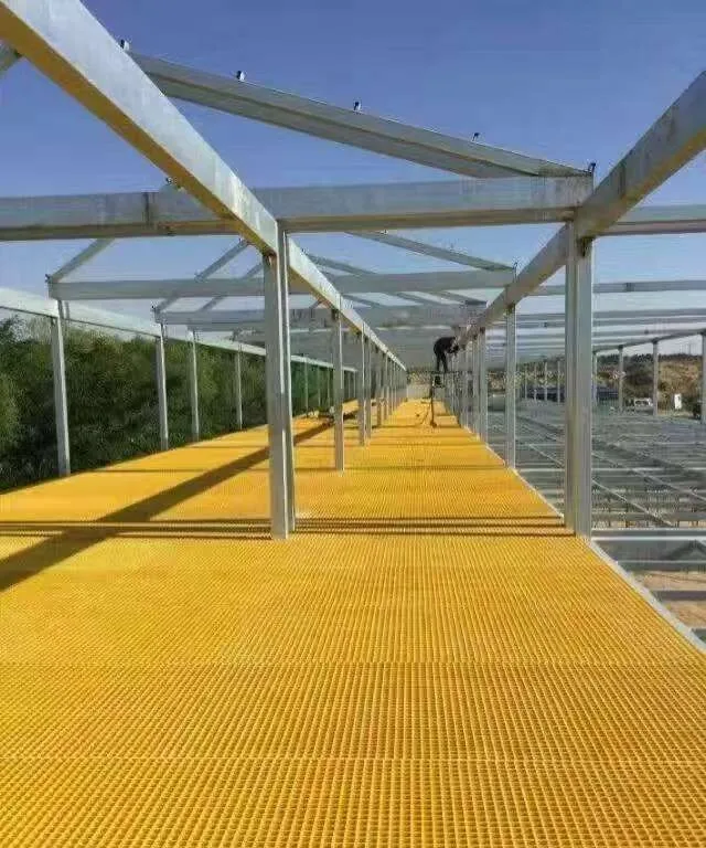
Separate Uniform, Point, Line and Wheel Loads
A uniform-load table does not answer every equipment case. A 2.5 kPa area load and a 2 kN equipment foot are different patterns and may produce different local bending and deflection.
For each load, record the unit, value, position and footprint. A wheel also needs its diameter and width. A moving load needs the route and possible impact. Dividing total equipment mass across the whole platform does not turn the load into a uniform area load.
The detailed load type and unit guide explains these differences. The row-selection rule is simpler: never combine a row written for one load pattern with a project defined by another.
Read Load and Deflection Together
The adopted reference table gives U as the additional uniformly distributed load in kPa and D as the paired deflection in millimetres. The values assume a single span, short-term loading, room temperature, untreated panels and a stated safety factor.
At 900 mm span:
- 38 mm pitch row: U 5.0 kPa, D 3.8 mm;
- 19 mm pitch row: U 7.5 kPa, D 4.7 mm.
At 1200 mm span:
- 38 mm pitch row: U 2.5 kPa, D 5.9 mm;
- 19 mm pitch row: U 2.5 kPa, D 4.8 mm.
If the project limit is 5 mm, the first 1200 mm pair fails even though its U is only 2.5 kPa. The second pair is below 5 mm, but that does not transfer the value to another construction or support condition.
This is why a table should be read row by row, not by finding the maximum load on the page. Read the U/D pair that corresponds to the project span and compare both with the project requirements.
Match the Support Condition, Not Just the Length
Bearing support affects the structural system. A panel simply placed across two supports is not the same as one continuous over three or connected to adjacent panels.
A table may also be based on all bars reaching their supports, a particular bearing width or a stated support arrangement. If any of these change, the row may cease to apply.
Show:
- the support at each edge;
- whether every bearing edge has continuous contact;
- the width available on each bearing surface;
- the position of clip holes;
- how panel joints transfer movement;
- how a cutout changes the support path.
Fixings restrain panels. They do not turn a missing support into bearing.
Check the Service Conditions Outside the Table
A room-temperature short-term table is not a complete service specification. Temperature, sustained load, chemical exposure, fire and repeated traffic can require separate evidence.
For a panel carrying a permanent equipment load, creep may govern before the short-term deflection value does. For a hot vessel or roof area, the resin stiffness at service temperature may differ from the table condition. For a chemical plant, the resin may need a separate exposure review.
Do not invent one blanket reduction factor. Ask which conditions the source table excludes and what additional calculation or product data applies.
A Useful Row Has an Audit Trail
Keep the source document, edition and page or table reference. Copy its exact field names into the quotation review:
- construction and pitch;
- span definition;
- supported edges;
- load type and units;
- deflection basis;
- safety or design basis;
- temperature and duration;
- exclusions.
If the row is later reproduced in a project submittal, the person reviewing it should be able to trace the number back to the same product and conditions.
This is also relevant to reports. A report titled only “FRP grating” may not identify the depth, mesh, resin or support used. It can document material tests without becoming a load table for every product.
Carry the selected row, conditions and source into the molded grating project datasheet section, so the quote and approved submittal cannot drift back to a generic table.
Our Factory Evidence Has a Defined Scope
Our factory test report HZTC/BG-24051102, issued on 17 May 2024, records a design load condition of 4 kN/m² over a 600 mm test span. The report does not identify the complete model, depth, mesh and resin specification for every molded row.
We therefore use it as material-level evidence, not as a universal table for 25, 30, 38 or 50 mm grating. When a project needs structural load evidence, the proposed construction and test conditions must match the document.
This distinction is important to an honest quotation. A test report can be real and useful while still having a narrower scope than the customer assumes.

How We Select a Row in a Real Enquiry
Our review starts from the project rather than from a stock table:
- Identify the grating family and the exact molded row.
- Mark supports, span and bearing surfaces.
- Record every load pattern and the required deflection limit.
- Find only the source rows with matching construction and support.
- Compare the complete U/D pairs at the required condition.
- Check service limits, openings, covers and fixings.
- Identify what remains unproven or requires a separate calculation.
A quotation may include a candidate row and still list a value that has to be confirmed. That is more accurate than presenting a convenient number as a project approval.
When We Would Stop the Load-Table Selection
We would not treat a row as approved if:
- the product row is not identified;
- only the depth matches;
- the span definition is unknown;
- the supports differ from the source;
- the load type or footprint is missing;
- the deflection limit is not stated;
- the table is being used outside its temperature or duration scope;
- an ultimate test load is being used as an allowable working load;
- the opened or covered assembly does not have matching evidence.
The answer in these cases is not to choose the strongest-sounding row. It is to clarify the condition, reduce the span, change the support or obtain evidence for the actual construction.
What a Complete Load-Table Inquiry Contains
Send the following:
- a plan and section showing supports and bearing widths;
- panel or piece dimensions with the clear span highlighted;
- load type, value and contact footprint;
- required deflection limit;
- proposed panel construction, if known;
- open, mini, covered or heavy-duty format;
- exposure temperature, chemicals and duration;
- openings, cuts and fixing positions;
- the load table, specification section or report the project expects.
If the drawing is incomplete, mark the missing values. An honest “unknown” is more useful than a guessed span or load.
Our Standard for a Reliable Table Selection
A usable row is not the one that looks strongest. It is the one that can be repeated from the same:
- product construction;
- span and support condition;
- load case;
- deflection basis;
- service environment;
- documented evidence.
When all six match, the load-table selection can enter the quotation. When one does not, the row is a lead for further review rather than approval.
Factory review
How We Review a Load Table Before Quoting
Our sequence keeps construction, support, load, deflection and evidence connected.
We match depth, pitch, bar construction and reinforcement before copying any performance value.
The drawing is reduced to a consistent clear-span and support description so it can be compared with the source table.
Uniform, point, line and wheel loads are kept separate, with their actual footprint and position.
Only rows that pass the project deflection limit and the applicable strength basis remain candidates.
Temperature, duration, cut-outs, covers and surface additions are checked against the table scope.
The quotation identifies the exact table, calculation or report used and any input still unresolved.
Evidence boundary
What Our Factory Report Can and Cannot Prove
A material-level report and a project-specific load selection are different kinds of evidence.

Product row identified before numbers
We do not use a depth-only match. The proposed pitch and bar structure must correspond to the table row.
Support condition written beside span
The review keeps bearing faces, clear distance and supported edges visible so a panel length cannot be mistaken for the structural span.
Load and deflection remain paired
A copied value includes its paired units, load pattern and deflection rather than only the maximum load.
Service limits remain visible
Short-term room-temperature assumptions are not extended into sustained load, elevated temperature or chemical service.
Factory report kept in scope
Report HZTC/BG-24051102 is material-level evidence for its tested samples and conditions; it is not presented as a universal load table.
Unsupported values become open items
If the evidence cannot match the project, the quotation states what calculation, test or design input is still required.
Engineer inputs
What to Send With a Molded Grating Load Question
A marked drawing and a clear duty description let the factory match a table row without guessing.
- Panel construction — Molded row, depth, pitch, bar geometry, reinforcement, resin and surface.
- Support and span drawing — Support locations, bearing widths, clear spans, panel joints and unsupported edges.
- Load cases — Uniform, point, line, wheel or equipment loads with values, units, footprints and positions.
- Deflection limit — The project criterion, including whether it is an absolute value, a span fraction or both.
- Service conditions — Temperature, load duration, chemical exposure and wash-down or outdoor conditions.
- Openings and fixing — Cuts, service openings, additional support, clip positions and removable areas.
- Required evidence — The load table, design calculation, test report or document scope named by the project.
Request a review
Send Your Molded Grating Load and Support Drawing
Include the construction, support condition, span, load and required deflection limit available today.
- Construction and support matched first
- U and D checked as a pair
- Evidence scope stated before quotation
Molded FRP Grating Load-Table Questions
Which molded grating load-table row should I use?
Can I use a 38 mm load table for every 38 mm molded panel?
Is the span in a load table the panel length?
Should I choose a row by maximum load or deflection?
Can I use a uniform-load table for a trolley or equipment foot?
Does the factory test report certify every panel?
Can values be interpolated between table rows?
This content was prepared and reviewed by Dengtai Industry’s technical and production team using the project conditions, available product data and applicable documents. Limits that require design, testing or approval are identified in the content. Content last checked: