Mini-mesh thickness guide
Mini-Mesh Grating Thickness and the Complete Configuration
Overall thickness is one part of the product row. The upper mesh, lower mesh, mass, support, load, deflection, surface and fixing have to be selected together.
Prepared by
Dengtai Industry
Published
·
Reviewed
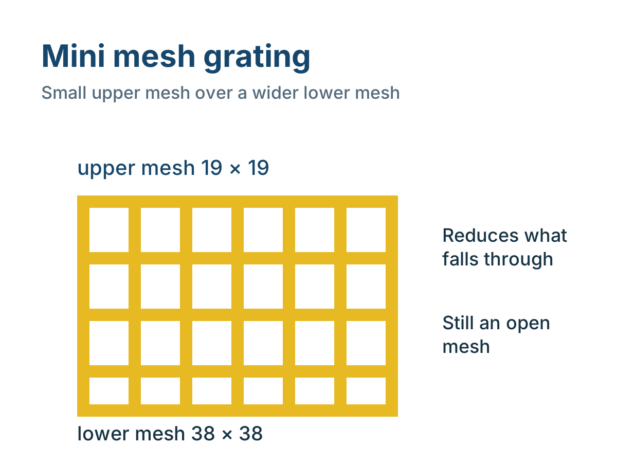
The section separates overall depth from the two mesh layers. The ordered row and evidence still come from the drawing.
Thickness vocabulary
Depth, Mesh, Mass and Capacity Are Different Questions
A complete mini-mesh row keeps all four attached to the same product.
- Overall depth
- The nominal top-to-bottom panel thickness. It determines the structural depth and installation height but does not identify the mesh, mass or allowable load by itself.
- Upper mesh
- The finer top grid that controls the visible opening and the first surface met by footwear, wheels or dropped objects.
- Lower mesh
- The wider grid beneath the fine upper layer. Its pitch and bar geometry may differ from the upper mesh and must be stated for the complete configuration.
- Mass per unit area
- The nominal mass for a defined mini-mesh row. It changes with depth, upper mesh, bar structure, resin and surface and is not a load rating.
- Clear span
- The unobstructed distance between effective support faces. The full panel length or cut-piece length is not automatically the structural span.
- Deflection limit
- The maximum accepted movement under the project load. The same panel can satisfy a load value but fail a stricter deflection limit.
- Matched load evidence
- A table, calculation or test whose product construction, support, span, load pattern and deflection criterion match the requested mini-mesh configuration.
- Configuration
- The complete ordered identity: depth, both mesh layers, panel size, bar structure, resin, surface, colour, fixing, fabrication and evidence.
Current schedule
Nominal Mini-Mesh Depth, Mesh and Mass Rows
Use the full row; equal depth can still represent a different upper mesh or mass.
Swipe horizontally to view all columns.
| Depth | Upper pitch | Panel format | Bar width | Nominal mass |
|---|---|---|---|---|
| 14 mm | 20 × 20 mm | 1247 × 4007 mm | 7.0 mm | 9.5 kg/m² |
| 22 mm | 20 × 20 mm | 1007 × 4047; 1247 × 4047; 1527 × 4047 mm | 7.0 mm | 14.5 kg/m² |
| 25 mm | 19 × 19 mm | 1220 × 3660 mm | 6.5 mm | 15.5 kg/m² |
| 30 mm | 20 × 20 mm | 1007 × 4007; 1247 × 4007 mm | 7.0 mm | 17.5 kg/m² |
| 30 mm small mesh | 11 × 11 mm | 1000 × 4000 mm | 8.0 mm | 21.5 kg/m² |
| 38 mm | 20 × 20 mm | 1007 × 4007 mm | 7.0 mm | 21.5 kg/m² |
| 38 mm | 19 × 19 mm | 1220 × 3660 mm | 6.5 mm | 22.5 kg/m² |
| 60 mm | 19 × 19 mm | 1220 × 3660 mm | 7.0 mm | 35.5 kg/m² |
Selection comparison
What Each Field Can and Cannot Decide
Avoid using thickness or upper mesh as a shortcut for the other fields.
Swipe horizontally to view all columns.
| Selection field | What it controls | What cannot be inferred |
|---|---|---|
| Depth | Structural depth, panel elevation and fixing height. | Upper mesh, total mass or a load rating. |
| Upper mesh | The visible opening and first contact surface. | Lower structural grid or clear span. |
| Lower mesh | Supporting grid and wider opening beneath the top. | Compliance with the upper opening requirement. |
| Mass | Self-weight, lifting and package calculations. | Capacity or deflection by itself. |
| Resin and surface | Chemical, fire, colour and walking-surface requirements. | Structural depth or the ability of the mesh to retain an object. |
| Load evidence | Performance under a stated construction, support, span, load and deflection basis. | Product suitability outside those conditions. |
Recalculation triggers
When a Mini-Mesh Thickness Must Be Reviewed Again
Any change in support, load, mesh or fixing can change the usable row.
Specify this if…
- The support layout and clear span are known.
- The required upper and lower mesh or clear opening are identified.
- The load pattern and deflection limit can be stated.
- The available fixing height suits the panel depth.
- The proposed resin and surface suit the exposure and cleaning.
Look elsewhere if…
- A thicker panel is being selected only because it “sounds stronger”.
- A 25 mm, 30 mm or 38 mm depth is being treated as a complete load class.
- One mini-mesh row's mass or load table is being transferred to a different mesh or support.
- The upper mesh is accepted without the lower mesh or clear opening.
- The support frame, bearing width or opening support remains undefined.
Configuration record
Eight Fields for a Mini-Mesh Thickness Review
Connect the actual structural condition to the complete product row.
Swipe horizontally to view all columns.
| Configuration field | What to record | Why it matters |
|---|---|---|
| Support layout | Support faces, clear spans, bearing width and panel joints. | Two-way mesh still needs a defined load path. |
| Load case | Uniform, concentrated, moving, repeated or stored load and location. | Different patterns create different local and global demands. |
| Deflection | Project limit and whether it is span-based or absolute. | A panel may meet load but exceed movement criteria. |
| Depth | Overall panel thickness and available frame or fixing height. | A deeper panel can alter structure, mass and installation. |
| Upper and lower mesh | Nominal pitch, bar width and clear opening at the selected plane. | The visible fine layer does not identify the hidden structural grid. |
| Mass | Nominal row and actual order mass where required. | Support self-weight and lifting needs. |
| Resin and surface | Grade, exposure, colour, grit or other finish. | Durability and function separate from structural depth. |
| Evidence and fabrication | Matching load data, cut sizes, openings, edge sealing and piece marks. | The delivered configuration must match the evidence. |
Mini-mesh grating thickness is one field in a product row, not a load rating. A 25 mm, 30 mm, 38 mm or 60 mm panel can have different upper meshes, lower layers, bar structures and mass values.
The order becomes comparable only when depth, both mesh layers, panel size, resin, surface, fixing, support, load and deflection are attached to the same configuration.

Separate Depth From Upper Mesh
Depth describes the top-to-bottom height of the panel. Upper mesh describes how closely the fine top bars repeat.
Two products can be described as 38 mm mini mesh and still differ:
- one may use a 20 × 20 mm upper pitch;
- another may use a 19 × 19 mm upper pitch;
- bar widths and the lower grid can differ;
- nominal mass can therefore differ.
Our current schedule, for example, includes a 30 mm row with 20 × 20 mm upper pitch at 17.5 kg/m² and a 30 mm small-mesh row with 11 × 11 mm upper pitch at 21.5 kg/m². Those are different products, not two ways of writing the same thickness.
Use the mini-mesh product table for the current nominal rows and the name-resolution guide when the starting name comes from another supplier.
Start With the Support Layout
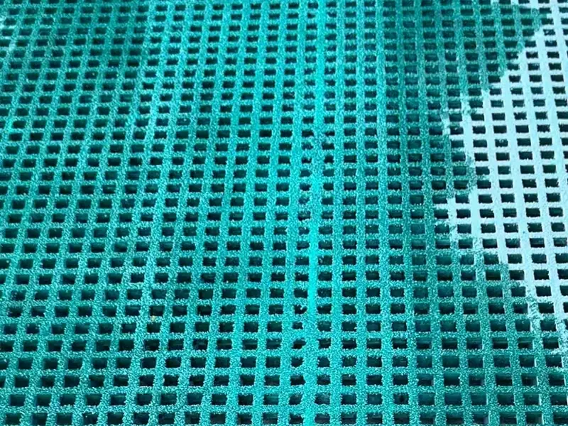
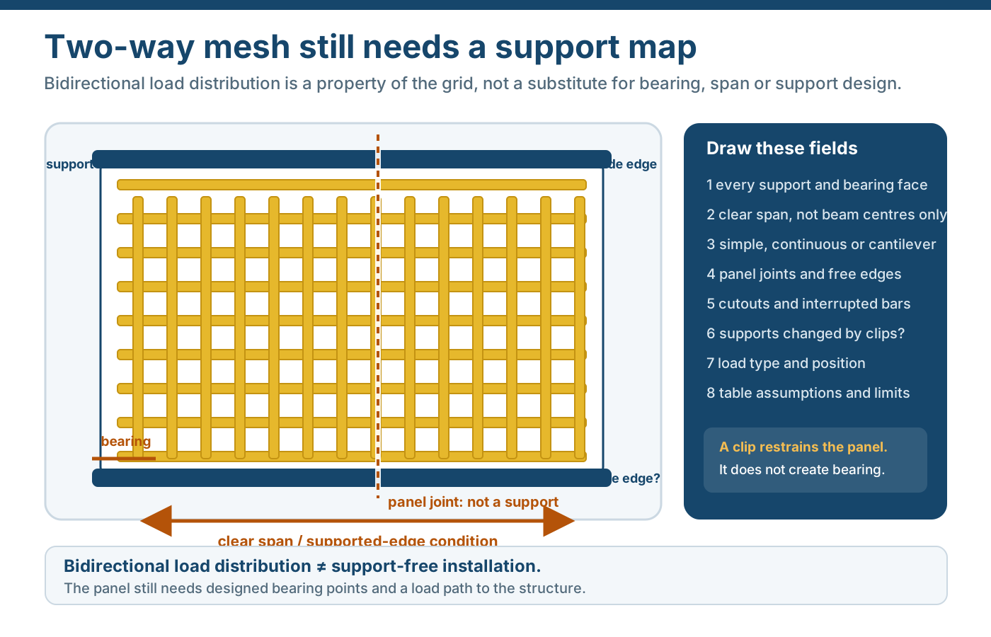
Mini mesh is usually a molded double-layer product. Its two-way grid still needs a defined support arrangement.
Before choosing a depth, mark:
- effective support faces;
- clear span in each direction;
- bearing width on each support;
- panel joints;
- free edges;
- cutouts and the bars they interrupt;
- any opening or equipment frame that needs local support.
A full panel length is not the clear span. A cut piece can look narrow enough for a 25 mm panel and still have a longer unsupported zone than expected because the supports are positioned differently.
Compare Load and Deflection on the Same Basis
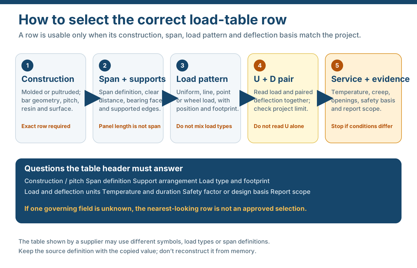
Thickness is often used as a shortcut because deeper panels can be stiffer. That does not create a universal sequence in which 30 mm is always adequate where 25 mm failed and 38 mm is always better.
For each candidate, record:
- uniform, concentrated, moving, repeated or stored load;
- load position and contact area;
- clear span;
- support condition;
- load duration and temperature;
- maximum accepted deflection;
- the product row and evidence that correspond to those inputs.
A table is usable only when its conditions match. Do not take a value from a standard-mesh panel, a different bar structure or a different support and apply it to mini mesh.
Our current public mini-mesh schedule publishes nominal depth, upper pitch, panel format, bar width and mass. It does not by itself provide a universal mini-mesh load rating. For a structural application, send the support layout, clear span, load type and deflection limit so the applicable calculation, table or test can be identified for the exact row. Do not use the standard 6 × 38 mm-row load values as a mini-mesh rating; the construction and mesh geometry are different.
Use Mass for Handling, Not as Strength
Nominal mass per square metre helps estimate:
- panel self-weight on the support structure;
- lifting and handling of a full panel or cut piece;
- packing and gross freight weight;
- whether a proposed panel split is practical.
It does not prove strength. A heavier row may contain more material, but the structural conclusion still depends on the section, bar layout, support, span and deflection.
The FRP grating weight guide separates unit mass, panel and piece weight from structural load.
Check the Fixing Height and Frame
The depth has to fit the installation.
Check:
- clip or clamp height against the actual panel depth;
- top of grating relative to adjacent flooring or nosing;
- available clearance below the panel;
- support flange width and bolt access;
- recessed or raised frame detail;
- removable panel weight and lifting access.
A deeper mini-mesh panel may suit the structural duty but fail the available frame pocket. A thinner panel may fit the frame but still fail the load or deflection criterion.
Keep Resin and Surface in the Same Row
Resin and surface are not substitutes for thickness or mesh.
Mini mesh can be discussed with polyester, vinyl ester and other resin directions where the selected product supports the combination. The walking surface may be concave, grit or another finish. Those choices affect chemical suitability, colour, cleaning, comfort and finished mass, but they do not create a load class.
For wet, oily or coastal service, choose the mesh and surface together with the cleaning method and sample review. Use the surface guide rather than assuming a fine mesh alone supplies slip resistance.
Treat a Cut Piece as a New Configuration
Cut size, openings and added fixings can change the delivered panel.
Record:
- top face and mesh orientation;
- finished size and clear span;
- interrupted bars and local support;
- drilled or slotted positions;
- cut-edge sealing;
- piece mark and quantity;
- actual piece mass where manual handling or lifting is critical.
A 38 mm panel cut into several narrow pieces does not preserve the original full-panel structural condition automatically.
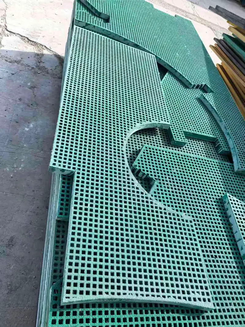
The Mini-Mesh Thickness Rule
Start with the support and load. Define the required upper opening and lower mesh. Compare candidate depths under the same span and deflection limit. Confirm mass, fixing height, resin, surface, cuts and evidence. Release only the complete row that matches the delivered configuration.
Selection sequence
From Supports to a Matched Mini-Mesh Row
Establish demand before comparing depth, mass or price.
Establish effective supports, clear spans, bearing width and joint positions.
Record the load type, position, duration and movement limit before choosing depth.
Keep nominal pitch, clear opening and the retention requirement together.
Compare depth, mass and the full structure under the same support and load conditions.
Check fixing height, cut sizes, openings, edge treatment and package handling.
Keep the load basis, sample reference and drawing revision with the selected product.
Evidence boundary
What a Thickness Figure Must Stay Attached To
Without support, mesh, load and deflection, the thickness number cannot support suitability.
One support condition
Clear spans and effective support faces are drawn before a row is selected.
One load and deflection condition
The candidate is compared with the same demand and movement limit.
One complete mesh geometry
Upper mesh, lower mesh and depth stay in the same row.
One order mass
Nominal and actual values are distinguished for lifting and freight.
One exposure
Resin, colour and surface belong to the same finished product.
One evidence package
The table, test, drawing and delivered configuration can be traced to one revision.
RFQ checklist
What to Send With a Mini-Mesh Thickness Question
Include the support and the full panel row, not only the depth.
- Support drawing — Support faces, clear spans, bearing width, joints and opening support.
- Upper and lower mesh — Pitch, bar width and clear opening or approved product drawing.
- Load and deflection — Load type, position, duration and maximum accepted movement.
- Candidate depth — Nominal thickness and available installation or fixing height.
- Panel and cut size — Full dimensions, quantity and any openings or finished-piece schedule.
- Resin and surface — Exposure, colour, grit or other finish and required evidence.
- Fixing and handling — Clip, frame, piece mass and lifting requirement.
- Evidence scope — Required load table, calculation, test report, sample or certificate and its configuration.
Request a review
Send the Support, Load and Mesh Data
We can compare candidate rows only when they are placed on the same duty.
- Depth compared inside the complete product row
- Same support and load basis across candidates
- Mass and structural evidence kept separate
Mini-Mesh Grating Thickness Questions
Does a thicker mini-mesh panel always carry more load?
Why can two 30 mm or 38 mm mini-mesh panels have different masses?
Is 25 mm mini mesh adequate for a walkway?
Does a smaller upper mesh increase load capacity?
What is the difference between panel depth and upper mesh pitch?
How does lower mesh affect thickness selection?
Can I use a standard molded load table for mini mesh?
Does this page publish a universal mini-mesh load rating?
Why is deflection separate from load?
Does grit or another surface change the thickness?
What if I only know the current panel is 38 mm?
What information gives a comparable mini-mesh quote?
This content was prepared and reviewed by Dengtai Industry’s technical and production team using the project conditions, available product data and applicable documents. Limits that require design, testing or approval are identified in the content. Content last checked: